After almost two decades of conducting compressed air system reviews, my interest has never wavered, because there’s always something new to learn. One never-ending source of learning opportunities is the integration of air dryers into compressed air systems.
In compressed air systems, every adjustment or system modification has consequences, so, before making changes, it’s important to understand how those changes will affect each piece of equipment. For example, simple things — such as lowering the compressor’s pressure set point, or failing to maintain the compressor’s aftercooler — can result in moisture contamination occurring out in the system. Why? Because the effects of these actions reduce the air dryer’s capacity. In this article, I address some ideas that can make your system more reliable.
System Design Philosophy
Systems are more reliable when all of the air is dried. Many plants have both instrument and plant air headers, but don’t dry the plant air, which shortens the life of tools connected to plant air drops, and potentially allows wet air to flow into the instrument air headers via inadvertent crossovers. Having a wet air header can result in winter freeze-ups and leaks at plant air drops.
Other systems use one main header to distribute wet air to each separate production area where a point-of-use dryer provides instrument air to that unit only. This approach multiplies the number of dryers, which increases maintenance and reduces reliability. One such facility had 42 point-of-use dryers with only 12 working. This meant that most of the instruments in the plant were operating off wet air that increased their failure rate.
A better way to design a system is to dry all of the air in the compressor station(s). In addition, if the plant isn’t sacrificing plant air in favor of instrument air, they can address areas with low pressure by opening or installing crossovers between the plant and instrument air headers.
Piping Characteristics for Oil-Free Systems
To prevent rust from plugging up refrigerated dryers or the prefilter of desiccant dryers, the upstream piping in “oil-free” systems should be stainless steel. Many manufacturing plants may be able to use copper pipe, but the environment in some facilities — like paper mills, chemical plants, and refineries —corrodes copper and silver solder, so almost all of them forbid their use. Where the upstream piping isn’t stainless steel, install a mist eliminator as close as possible to the inlet of refrigerated dryers or a desiccant dryer’s prefilter. Installing a standard coalescing filter is less efficient, because they create a significant pressure drop and increase maintenance.
Temperature Characteristics
The greater the differential between the compressor discharge and the ambient temperatures, and the greater the distance between the compressor and dryer, the more likely it is for moisture to slug filters and dryers, and saturate desiccant. If temperature differentials and/or distances are significant, water will condense out of the compressed air stream as the air travels between the discharge of the compressor and the dryer. This water gathers in low points of the piping run and can travel in slugs of liquid as the compressed air flow propels it along. It’s important to know that coalescing filters aren’t designed to handle slugs of condensate, and that moisture and oil vapors pass through them. Also coalescing filters prefer water over oil. These are some of the reasons filter manufacturers recommend installing a particulate filter upstream of a coalescing filter. A high temperature differential can also result in moisture condensing between the prefilter and the desiccant bed. Insulating the piping between the prefilter and the desiccant bed will prevent moisture from saturating the desiccant.
Mist eliminators can handle slugs of condensate, but vapors also pass through them. They can also be overloaded by a large, constant flow of liquid. Their low pressure drop and estimated 10-year element life are advantages of using a mist eliminator. A precooler, with a moisture separator or knockout pot installed upstream of the dryer, can prevent condensate from collecting in the pipe and slugging the prefilter and/or dryer, or condensing between the desiccant dryer’s prefilter and its desiccant bed.
The compressor’s aftercooler isn’t considered a precooler unless chilled water is running through it. The purpose of a precooler is to reduce the temperature differential between the compressor discharge and the ambient temperatures. A precooler can also save energy when installed upstream of many styles of heated desiccant dryers. Installing a receiver, instead of a mist eliminator upstream of a desiccant dryer, can capture the condensate slugs, but many desiccant dryer installations will also require insulating the piping to prevent condensation from occurring between both the receiver and the prefilter, and the prefilter and the desiccant bed. Don’t assume this won’t occur in your system just because your plant is located in a warm climate, because we’ve seen it occur throughout the Gulf Coast.
Desiccant Dryer Failure Issues
In desiccant dryers, large quantities of compressed air can be lost when a valve on the dryer fails (in addition to purge air, stripping air, and cooling air losses). In some plants that have sufficient online backup compressor capacity, these losses can go unnoticed. In other plants, they create production outages that cost millions. Installing flow meters up and downstream of each dryer and then monitoring the difference between them can locate the air loss. Installing a trip valve in the dryer’s purge line, that’s set to trip at a specified low pressure, can prevent the loss of production. However, a trip valve or a dew point monitor alarm is required to notify operators of the problem. One dryer manufacturer automatically closes the purge exhaust valves on falling pressure, but this approach doesn’t protect the system against a purge exhaust valve failure.
Installing a check valve at the discharge of each dryer isn’t a reliable solution to protect the system against a dryer valve failure, because it prevents access to upstream compressor capacity. For example, a large refinery had check valves installed downstream of their dryers, but when the dryer downstream of two compressors failed, it dumped the capacity of both compressors to atmosphere, which shut down the plant. The cost of that outage was in the millions.
Sizing Dryers
Using the rated pressure of the compressor to size the dryer is a common mistake. Dryers are rated for a certain pressure, and operating lower than that rated pressure reduces the dryer’s capacity and increases the pressure differential across the dryer. For example, a rotary screw compressor rated for 125 psi operating in load/unload mode will typically cycle between 115 and 125 psi, so the highest average pressure will only be 120 psi. Many plants operate their 125-psi compressors at lower pressures, so be sure to verify the actual average operating pressure of the compressors and take into consideration any pressure drop between the discharge of the compressor and dryer.
The scfm capacity of an air-cooled refrigerated dryer is directly related to the dryer’s inlet pressure and inversely related to the inlet and ambient temperature. They are typically limited to a maximum ambient temperature of 110⁰F. Our experience shows that if the ambient temperature can exceed 105⁰F, or the dryer is going to be installed in a dirty environment, a water-cooled version should be installed.
Some non-cycling refrigerated dryers can’t maintain their rated pressure dew point (PDP) when flow drops below 47 percent of their rated flow, so review the dryer’s CAGI data sheet before purchasing the dryer.
Plants with large compressed air systems, which only require a +40⁰F PDP, should consider installing a redundant style refrigerated dryer, because when a refrigeration compressor fails, they prevent wet air from flowing out into the system.
Desiccant dryers are sized based upon their inlet pressure and temperature. The inlet temperature of a standard dryer is typically limited to a maximum of 120⁰F, because over that temperature the adsorption ability of activated alumina, the desiccant most often used, decreases significantly.
A “heatless” dryer can lose its heat of regeneration when located outside in lower ambient temperatures. So, you should either insulate and heat-trace the towers, or build sheds around them and install radiant heaters in the sheds. The word “heatless” is in quotations because the dryer actually uses the heat given off when the desiccant adsorbs moisture to regenerate the desiccant when the tower is in the regeneration portion of the dryer’s cycle.
A desiccant dryer’s rated capacity is its inlet capacity, which is almost always less than its outlet capacity. For some styles, manufacturers will beg to differ. However, we’re referring to actual field observations and not the intentions of the original design. For example, “heatless” desiccant dryers have a combined 15 to 17 percent purge and depressurization air loss. While externally heated and internally heated desiccant dryers have purge air losses of 7.5 and 3 to 4 percent, respectively, they also have a cooling air cycle that starts after the purge air ends. Blower purge desiccant dryers have a cooling air cycle that consumes 5 to 7.5 percent of the dryer’s capacity. Heat-of-compression dryers can have a stripping air cycle as well as open drainage losses. The reality is that drains fail, and, more often than not, they are bypassed rather than repaired, so these losses need to be considered in the design of the system.
After sizing a dryer, select the next larger size. This is a rule we don’t vary from, because installing the exact size dryer required, for various reasons, almost never works out. For example, if end uses consume 1000 scfm, installing a 1000 scfm compressor and a 1000 scfm “heatless” dryer will only deliver 850 scfm. This application requires installing a 1200 scfm compressor along with a 1200 scfm “heatless” dryer. However, because we prefer to install one larger size dryer, we would select a different style dryer that has less purge losses. For example, installing a 1200 scfm compressor along with a 1500 scfm externally heated dryer delivers 1087 scfm.
Paralleling desiccant dryer packages can lead to unbalanced flow and poor system PDP.
Paralleling Dryers
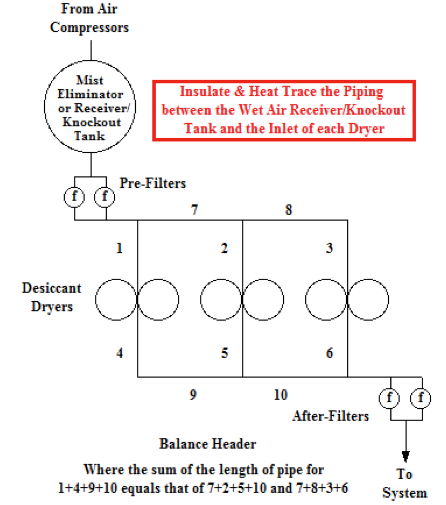
Paralleling desiccant dryer packages can lead to an unbalanced flow through the dryers and a poor system PDP. To maintain a reasonably balanced flow through the dryers, remove the prefilters and afterfilters from the packages and parallel them upstream and downstream of the packages. Also, install a balance header or oversize the piping between the prefilter, dryers, and afterfilters. As mentioned above, some environments where the dryer is installed will require installing a mist eliminator or knockout tank and insulating the piping between it and the dryer inlet.
Dew Point Spike Issues
Paralleling multiple heated desiccant dryers can result in a poor PDP. For example, Figures 1 and 2 display the PDP graphs of two heated desiccant dryers measured at their discharge. The first graph is the PDP of a blower purge dryer dedicated to an “oil-free” rotary screw compressor, while (Figure 2) is the PDP of a heat-of-compression (HOC) dryer, which is located downstream of three centrifugal compressors. Both dryers operated on a fixed 8-hour NEMA cycle, or 4 hours on each tower. The red line indicates the PDP.
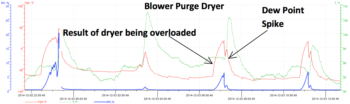
Figure 1: The PDP of a blower purge dryer dedicated to an oil-free rotary screw compressor - Click here to enlarge
Figure 1 is an example of sizing the dryer to match the capacity of the compressor. In this case, the compressor was rated at 1538 acfm, and the dryer was rated at 1500 scfm. The dew point was measured during the winter when the capacity of the compressor was 1567 scfm. In addition, the compressor’s aftercooler needed to be cleaned, so its discharge temperature was 105⁰F. The rotary screw compressor was used as a trim compressor, but was fully loaded for 1.5 hours when the HOC dryer was in the stripping air portion of its cycle. Note that after spiking, the PDP drops to between -50 and -70⁰F.
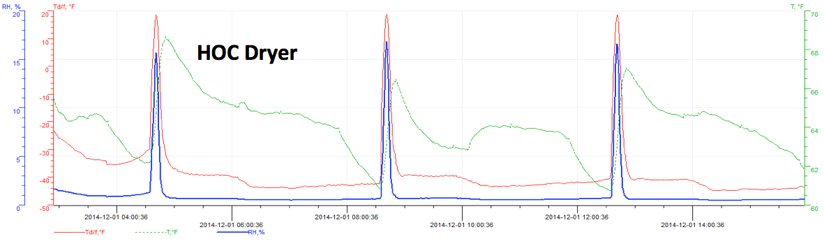
Figure 2: The PDP of a heat-of-compression dryer - Click here to enlarge.
Figure 2: The PDP of a heat-of-compression dryer shows the PDP spiking to +20⁰F, after which, it drops to between -40 and -45⁰F. The HOC dryer was rated for 10,000 scfm with an actual flow of 7700 scfm. The PDP would probably drop to between -50 and -70⁰F, and a spike wouldn’t go above 0⁰F if a preheater was installed to increase the inlet temperature from 220⁰F to 350⁰F.
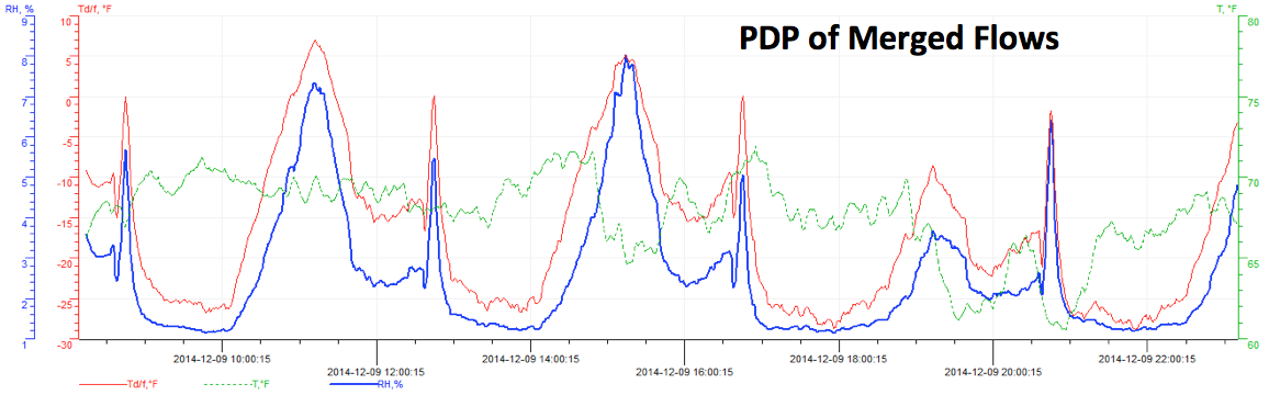
Figure 3: The combined PDP of the two dryers after the flows merged - Click here to enlarge.
Figure 3 shows the combined PDP of the two dryers after the flows merged. The graph shows the PDP spike of each dryer, along with the overloading of the blower purge dryer. Depending upon the demand, the average PDP varies between -10 and -15⁰F and -15 and -20⁰F, which explains the freeze-ups that were occurring.

Figure 4: The effect on the PDP of synchronizing the dryer cycles - Click here to enlarge.
Figure 4 shows the effect on the PDP of synchronizing the dryer cycles. Synchronizing the dryers reduced the PDP spikes to one every 4 hours and improved the average PDP to between -25 and -30⁰F. Also, the PDP spike reduced from +20 to less than 0⁰F. Installing a preheater on the HOC dryer, raising the discharge pressure, and cleaning the aftercooler on the rotary screw compressor will further reduce the PDP spikes and the average PDP.
These PDP spikes don’t appear to mix with one another in large chemical plants and refineries where the compressors and dryers are distributed throughout the plant. However, in smaller plants or wherever the heated dryers are paralleled, it can be an issue.
Conclusion
Part II of this article will cover other ways in which end users can make their compressed air systems more reliable. Topics will include the difference between operating a desiccant dryer in a fixed cycle opposed to demand mode, operating heated desiccant dryers with cooling air turned off, and dealing with the unintended consequences of dedicating a desiccant dryer to a compressor. Additional commentary on this article will also be provided, since, as mentioned previously, there’s always something new to learn.
For more information, contact Chris Beals, tel: 303-771-4839, email: cbeals@earthlink.net.
To read more about Compressed Air Treatment, please visit www.airbestpractices.com/technology/air-treatment.