The hardest part about evaluating the capabilities of various central air management control systems for multiple pieces of compressed air equipment, specifically air compressors, is that they all do the same thing in their marketing sales material.
Productivity and profits are very directly linked to the compressed air system, as is waste elimination. High performance central compressed air management systems can respond quickly to even extreme system fluctuations, improving productivity and minimizing energy waste. This is accomplished with modern software systems analyzing and processing appropriate data and triggering proactive actions - before the dynamics effect the compressed air production system. This is an advancement as opposed to the old style central air system’s action occurring after the event or events. Do all central air management systems do this with all units? No, they certainly don’t! To start with, ask appropriate questions:
- Can you handle positive displacement air compressors and dynamic (centrifugal)? Separately? Together?
- Can you handle all brands? All types of capacity controls? Old and new units?
- Will your central air system tie in the auxiliary equipment such as dryers, cooling towers, pumping stations, crossover valves (high pressure to low pressure)?
- Can the system be accessed remotely?
- Will it notify appropriate personnel for service if required?
- What is the data analyzing protocol?
The list can go on and on but in the end you will still have a lot of systems to look at and fit to your circumstances.
Where have we come from?
For many years, a central control or air management system was really just a sequencing system that brought compressor units on and off from a preset alignment against a sensed compressed air system pressure.
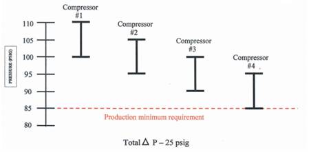
After a simple blow-off valve, which “blows off” excess air when maximum pressure was needed, the next step compressor central control system was the cascade type pressure control. Air compressors were set up on descending preset operating bands that with four units as shown here, with a 10 psig operating band required 25 psig from high to low system pressure just to operate all units.
Typical Cascade Control Settings
Through the 1980’s and 1990’s, improvements began to take shape. With the development of electronics, the operating bands were tightened, thereby saving energy. The PID controller was used to identify the rate of change and combine this with system that set a single target system pressure and develop methods to bring on only the proper alignment of units to do the job.
Easy to say – not so easy to do.
During the 1990’s and on into the twenty-first century, central air management system protocol development followed this path with many achievements
Note: Advanced electronic controls allowed a much smaller or tighter operating band with this cascade system; a significant improvement.
The most talented controls personnel were also often the least knowledgeable compressed air personnel and vice versa. There was a tendency to reconfigure all rotary compressor controls (modulation, variable displacement, and sometime even variable speed drive) to 2-step or load/no load unit capacity control to make them “easier” to work into those “tried and true” programs, which always worked. Sometimes this worked well, other times it did not depending on the available unit selection and local interconnecting piping. Lubricant-cooled rotary screw compressors further complicated this situation as they all require a specific minimum off time to be able to blow down to full idle and lowest input kW at idle. This time delay can range from 7 seconds to 3 minutes depending on the size, model and age of the unit. To reach these results often required (and still requires) correct piping and the performance is very “storage dependent”.
And so, technology progressed with many systems still trying to react faster after the system “event” to match the system dynamics. Tighter bands, more storage at higher pressure (more energy to produce), to buy more time to react to the system dynamics.
In many cases these worked fine depending on the situation; however, here is one that did not work and why:
At a powdered metals plant in North Central Pennsylvania, the operation has the following demand profile with established targets for the control system:
| Demand Profile | Central Air Management Target |
| Average flow = 1750 scfm | Average flow = 1750 scfm |
| Maximum flow = 2150 scfm | Maximum flow = 2150 scfm |
| (This is a very tight demand profile and should be relatively easy to respond to effectively.) | (1) base = 1800 scfm |
| (1) trim = 440 scfm | |
| 100-hp part-time | |
| Nominal operating pressure = 100 psig | Pressure Range = 100 ± 2 psig |
The air supply consisted of:
- (1) 400-hp 2-stage variable displacement rotary screw 1850 scfm at 100 psig
- (3) 100-hp single-stage constant speed inlet modulation control 440 scfm at 100 psig
- Central Air Management Control System Design Parameters:
- Tie all four unit to a central air management system; system pressure based.
- Convert all units to load/no load control (2-step) because:
- The supplier felt it “was the most efficient”, and
- “This was the only protocol” that existed in the software.
- Operate a ±2 psig target band.
They also installed two 3,500-gallon air receivers as storage to create the allowable permissive time for the controls to react.
Note: The piping in Figure 1:
- Single point entry and exit to the first air receiver. Air cannot leave the receiver when the line pressure is higher than the receiver. As soon as the trim compressor loads in, the line pressure rises more rapidly than the receiver, blocking the stored air within seconds and rapid response is destroyed.
- The second receiver can only get air to the system control after the pressure falls in the first receiver. In this case, it may never get out.
- The pressure flow controller is there to stabilize system pressure but it does have a 5 psig pressure loss built-in. The 5 psid loss will increase as the entry pressure falls. This item would not be required in a properly controlled system because the central controller can deliver a steady lower pressure.
- If the 400-hp unit is unloaded, it must fight its way past all the 100-hp units that are loading into the header with 90° crossing tee’s in order to reload. The back pressure causes it and the 100-hp units to short cycle. The actual operating pressure band ranges from 103 to 117 psig with all the action taking place in the piping which is at a higher pressure than the receivers (103 psig) most of the time effectively blocking them from the system.
Operating Sequence
The 400-hp unit is at base load at a lower average demand flow (1,600 scfm) even than its full load flow of 1,750 scfm unloaded. 1,750 scfm is removed from the system drawing 1,600 scfm with full 7,000-gallon storage available immediately. It is not due to delay in “turning the air around” – cycle time would be a little less than 40 seconds before the first and/or second 100-hp unit loaded in, the 400-hp is still blowing down. The piping pressure rises faster than the receiver’s stored air, effectively blocking its exit from the receivers. The 400-hp reloads and the cycle starts all over again.
The Tale is in the Tape
24-hour trended curves from the new central air management monitoring system shows:
- Three units on line - all at part load
- 2,948 cfm on line / 1720 cfm average demand / base Unit 1, 1800 cfm
- Peaks to 1,900 – 2,000 cfm
- Pressure swings from 103 to 117 psig
- The 2-step controller has a much slower response time than either the variable displacement or modulation control. Therefore, it cannot respond as effectively to these system dynamics.
“5-step” spiral valve control on 400-hp compressor converted to 2-step load/no load control
What happened?
Incorrect piping and software incapable of utilizing the variable displacement capacity control system interfered with proper component operation. The piping configuration blocked the timely use of the large air receivers (7,000-gallon).
“Core” Design Fault
Fault is due to a lack of a central air management control system to take advantage of the positive operating characteristics of a variable displacement control (5-step). If the protocol in the software could interpret the load position this problem would have been averted. As the pressure rose to the unload point, the 400-hp unit would have gone to 87-88% flow (1,575 scfm; a drop off of only 225 scfm). The 100-hp would not have come on and the system would be stable. This would occur all the way down to 900 scfm. Above 1,000 scfm, the 225 scfm redirection would not cause the collapse of the system. The same level of storage would not have been required for proper operation and the pressure/flow controller could have been eliminated (capital cost and 5 psid). Proper piping design will still be required.
What this Shows
A 2-step or load/no load control system sensing pressure to control at best is only a reactive type system and cannot begin to operate until after the system pressure move has occurred. We can streamline these actions, build in permissive time, but the more complex the design, the more opportunity for problems and the less user friendly the total program is. In the case study shown here, the plant manager and plant engineer thought everything was ok for a year until they looked at their recorded data! No calls, no problems; but energy dollars are going down the drain.
Over the last decade, the system pressure based central control systems have developed more and more effective ways to operate with a narrow control (avoiding excess pressure) and holding the production header pressure very tight (±1 psig). However, often this suggests or even requires a large storage receiver of compressed air and a pressure flow controller (demand expander, intermediate controller, pressure regulator, etc).
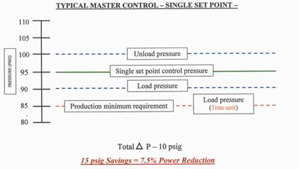
Eliminating the cascade system has been accomplished by software that establishes a single operating system pressure band control to which all the units respond. To oversimplify, these systems usually still run on a single load or no load local capacity control on the compressors.
A signal goes to each unit, full load or full unload. All units are kept at full load except the trim unit. Unneeded units are at idle or shut off. Further performance is written into the software calculating the rate of pressure rise or rate of pressure falling to select the appropriate response in compressor size to delete or add from the available units.
Other programs may incorporate specific trending in the software analysis to help estimate the best action “after the event”. This can be very helpful because it will dampen any quick response to a random short term pressure rise or fall and help stabilize the system.
Other such informational processes on available machine sizes, peak loads, minimum loads, etc, can all be worked in. This increases the transfer and processing of high volumes of data and the complexity of the protocol but does enhance the flexibility.
Summary
We have taken the operating system pressure based central control air management and control protocol about as far as it can go. Regardless of its response time, no action can be taken until after something has happened to the system, i.e. too low of pressure, or too high. It’s only method to interpret what is happening is system pressure. This will miss any type of malfunction that impedes the compressed air flow such as:
- Collapsing inlet filter hose connection at load (we have seen this several times)
- Inlet control valve out of adjustment, or not executing full travel
- Discharge check valve stuck partially open
- Heavily fouled separator
- Local capacity control out of adjustment or failed
- Many other as well.
 |
"High-performance central compressed air management systems can respond quickly to even extreme system fluctuations, improving productivity and minimizing energy waste." - Hank Van Ormer, Air Power USA |
During the 1990’s, great progress was made using flow based data, individual unit load position, reactive specific power (efficiency), and particularly with mass flow compressors (centrifugals), ambient or inlet air conditions.
From the late 1990’s into the 21st century, new advancements into software protocols were developed to take action on the software predicted event before the event occurred and therefore be more proactive. Built into these modern protocols were such things as:
- Relative efficiency of each unit of compressed air supply, considered at full load, type of capacity control, and part load capability to activate sequencing/alignment
- Permissive start and/or reaction time required
- Low and high pressure limitations
- All units are lined up in a preferred sequence. The preferred sequence is modified when operating conditions call for it.
- System pressure, compressor discharge pressure, storage pressure, system flow, unit flow, motor input kW (power), all combined and compared real time to accurately portray the actual system operating conditions.
- Changes in flow demand are picked up at the very beginning of a potential cycle and proper required action, if any, can be started before any effect is showing. Timely control action can often completely avoid any effect.
- Capable of handling all types and brands of air compressors in a single system.
- Capable of handling and controlling auxiliary equipment such as dryers, filters, cooling system, etc. They include such things as controlling the adjustable purge on a desiccant dryer and/or monitoring the true performance of a refrigerated or desiccant dryer.
- Offer a customized remote monitoring system which can be viewed from anywhere in the world with a computer and web browser.
- Preventative service maintenance reminders.
- Notify appropriate contacts when service is or has been required.
- Remote control of system with password protection.
- Communicate to one or several central locations.
The list of control and monitoring opportunities goes on and on. The modern central air management system is more than a sequencer. They can be a great working partner to help you monitor and keep those hard won compressed air energy savings.
For more information please contact Hank Van Ormer, Air Power USA