A Canadian fiberglass plant has completed a lengthy compressed air improvement journey and achieved significant efficiency gains by applying “the systems approach.” Along the way, the company ran across many frustrating problems, the solutions to which were only determined after the entire system was monitored holistically using data loggers. The overall compressed air audit led to a reduction in energy usage of 48 percent, yielding savings worth \$17,500 per year. The project also qualified for a large utility incentive of \$32,000 with a calculated payback of 4.4 years.
The company makes fiberglass components for the type of highway buses we see on most interstate roads. Using lighter materials like fiberglass reduces the weight of the vehicles and makes them more fuel-efficient. Due to the size of the buses, some of the parts are very large. The site uses compressed air to supply hand tools and various compressed air-powered production machines and processes. When the parts are made, compressed air is used to hold the parts in the molds using pressurized bladders. At the same time, vacuum is used to suck the parts into the molds to make a perfect fit. After the parts are set, they must be cut out of the mold with air-powered cutters, and then finished using various air-powered grinders, sanders, polishers and painting systems.
A Long History of Compressed Air System Changes
Starting in 2004, the compressed air system has been constantly changing as production levels have increased. The site originally had three 30-hp, two-stage, air-cooled reciprocating compressors running to feed plant demand. But these compressors started to experience problems as compressed air flows increased. Air-cooled reciprocating compressors are often adequate for lightly loaded systems in well-ventilated environments, but as duty cycles increase, the units typically overheat, causing failures of the internal parts and valves. The compressed air flow produced by these very noisy machines is often extremely hot and filled with lubricant carryover, which requires special, high-temperature dryers and filtering. To solve these problems, a special after-cooler was installed to reduce the air temperature before it entered the air dryer, allowing a standard dryer to be used.
After a few years of maintenance headaches, the company decided to switch to a rotary screw air compressor. Rather than installing a standard fixed-speed air compressor, a more efficient variable speed drive (VSD) air compressor was purchased with a cycling air dryer, a pressure/flow control valve, and mist eliminator filtering. No changes were implemented on the demand side of the system. Measurements determined the new air compressor, dryer and filters lowered plant pressure, saving about 31 percent compared to a fixed-speed compressor. The lower pressure resulted in electrical savings worth \$7,700 at today’s prices. For backup, the existing reciprocating compressors and after-cooler were left in place.
Load Increase Causes Pressure Problems
This system worked well on one air compressor for a number of years, but as the compressed air load increased and the installed equipment aged, pressure problems started occurring. Data loggers were installed on the system to see if the problem could be determined. Even though the VSD air compressor was set to the highest pressure possible, 140 psi, the system had trouble keeping up with demand—with main header pressure often falling as low as 80 psi. This was causing major problems on the demand side. Compressed air hand tools were operating with reduced power and often stalling, which increased the time it took to process each part.
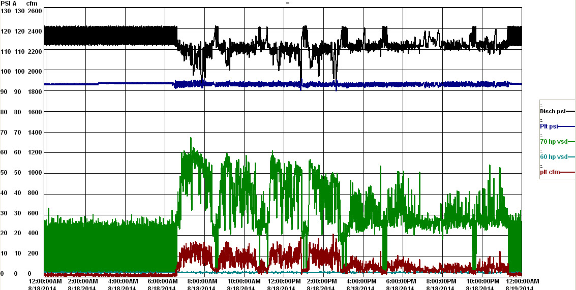
Figure 1: Even with very high air compressor pressure, the plant pressure was inadequate due to component failure.
Click here to enlarge
To attempt to increase the plant pressure, the old reciprocating air compressors were placed into service. Unfortunately, the pressure coordination strategy caused the reciprocating units to run at 100 percent duty cycle, which is fatal for air-cooled units of this type. One after another, the units failed. Even worse, the hot lubricant they expelled coated the internal surfaces of the after-cooler and clogged the pneumatic actuator on the pressure/flow controller, causing other problems. Detailed pressure measurements showed that during peak plant flows there was a 20-psi pressure differential across the contaminated after-cooler and flow controller. The data also showed that the regulator was no longer accurately controlling the pressure due to internal problems. In addition to this, the peak plant demand was exceeding the capacity of the available air compressors, allowing the system pressure to drop below the lowest levels required for critical production machinery. An increase in capacity was required.
Salvaged Air Compressor Added
The company had obtained an older screw compressor in a plant closure, which was installed in an attempt to increase capacity. However, this air compressor was only rated for a full-load pressure of 115 psi—much lower than the main compressor set point of 140 psi. This made efficient coordination of the compressors impossible. The unit had to be placed in modulation mode to produce a high enough pressure. During times it was not required, it ran constantly, because it lacked any shutdown timer. The unit ran many hours while lightly loaded, greatly reducing the efficiency of the compressed air system.
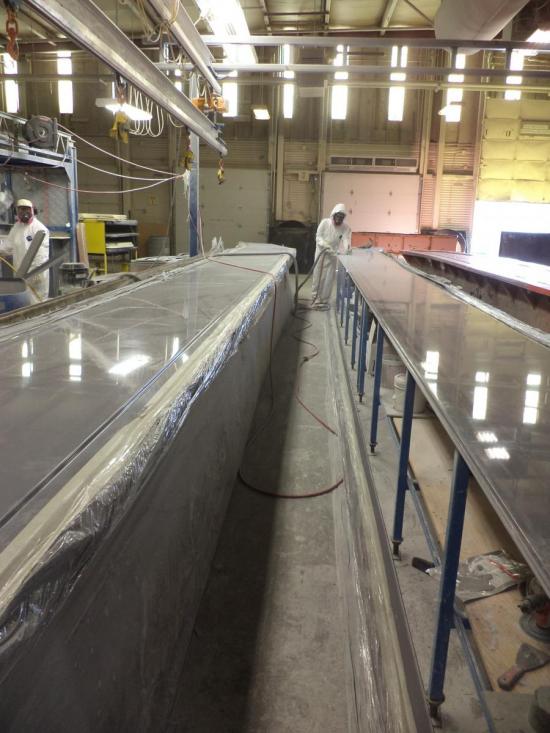
Figure 2: Hose selection and poor connection practices cause poor compressed air tool performance.
Despite the addition of more capacity, the plant continued to experience poor tool performance, especially at a critical mold where very large pieces were cut with a special air-powered tool. Production was suffering, so a compressed air auditor was called in to have a look.
Compressed Air Audit Finds Excessive Pressure Differential
From the initial data logging, the problem with the clogged cooler and malfunctioning flow controller was very obvious. The cooler was removed and regulator bypassed. Surprisingly, however, this did not completely solve the problem with poor tool performance. Further investigation was done at the end use, and found a poorly designed supply system feeding this most critical cutting tool. A special test was performed to measure the pressure gradient in the supply lines using a T connection with a test gauge. The test gauge was inserted into the line directly before the final tool connection. With no tool operation, the line pressure was at 118 psi, but once the tool trigger was pulled and the unit started operating, the input pressure fell to 44 psi. Since the rating of the tool is 90 psi, poor performance was a result.
In looking back towards the system to the main header, the hose system feeding the tool consisted of a total of four standard 1/4-inch quick connect couplings at various points and a 50-foot section of 1/4-inch hose mounted on a hose reel. A hose of significant length is required to provide sufficient mobility to reach all locations along the length of the large molds. Calculations confirmed the expected pressure differential of this configuration. The hose system was undersized.
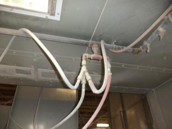
Figure 3: Questionable connection practices caused huge pressure differentials in some areas.
Examining End Uses for Potential Reductions
The auditor also thoroughly examined other end uses in other areas of the plant for possible reduction opportunities. Leakage levels were high, consuming 45 percent of average compressed air flows during weekend non-production times. Air-powered agitators were allowed to run to mix solvents during non-production hours when no mixing was required. A significant waste of compressed air was found in the grinding area where pulse-type cartridge filter cleaners had been adjusted incorrectly. Instead of sending a cleaning pulse of compressed air every few minutes, the sequencing timer had been adjusted to pulse every 2 seconds. Even with this increase in frequency, the filter cleaning performance was not as expected.
Figure 4: Poorly adjusted pulse filter cleaning system wasted compressed air
Extra Savings in the Vacuum and Ventilation Systems
While assessing the system, the auditor noticed that a vacuum system located in the compressor room was running excessively. Further study using data loggers revealed that the vacuum pump control system had failed, causing two 15-hp pumps to run all the time—when only one was required for typical loads. The other vacuum pump was only required for short duration peaks.
In addition to this, it was noticed that the compressor room ventilation system was using 100 percent outside air draw for compressor cooling due to the dusty plant environment. A 20-kW electric heater ran full time in winter to temper the compressed air to prevent freezing up the air compressor’s after-cooler. Calculations showed that the air compressor was producing enough heat to temper the room with the heat of compression.
Comprehensive Compressed Air System Improvements
Various system improvements were implemented to correct the situation. They included:
- Critical tool hosing was upgraded to 3/8 inch, and the number of quick-connect couplers was reduced to one full-flow connector. The cutting tool now sees 90-psi operating pressure.
- Leakage was repaired and mixers turned off on the weekend. Pulse cleaners were outfitted with receivers to boost pulse force, allowing a reduction in operation frequency and saving compressed air.
- A pressure/flow controller was replaced with a unit sized for full compressor flow.
- Additional storage receiver capacity was installed to help with peak demands.
- Compressor room piping was upgraded to a larger size to reduce pressure differential.
- The air dryer was upgraded to cycling style with heat directed to the compressor room.
- A new VSD air compressor was installed, with an old VSD compressor used as backup. Compressor discharge pressure was lowered to 110, and plant pressure reduced to 92 psi.
- Heat of compression is now directed into the compressor room with thermostatically controlled dampers. The 20-kW heater is now turned off.
- Vacuum system control was upgraded to reduce operating time. The vacuum system is turned off during weekend hours.

Figure 5: Plant pressure and compressed air flow during the off hours were greatly improved after the projects.
Click here to enlarge
As a result of the improvements, the compressed air system, the room heater, and the vacuum system energy consumption has been reduced by 48 percent for savings worth \$17,500 per year. This project qualified for a substantial utility incentive of \$32,000 with a calculated payback of 4.4 years, not including the increased plant productivity.
This project illustrates the benefit of improving the whole system, including the end uses and distribution system, rather than looking at just the air compressors.
For more information visit the Compressed Air Challenge® website or contact Ron Marshall, Marshall Compressed Air Consulting, tel: 204-806-2085, email: ronm@mts.net.
To read more System Assessments on End Uses in plants, please visit www.airbestpractices.com/system-assessments/end-uses.