Introduction
This food container plant spends \$1,028,672 annually on energy to operate the compressed air system at their facility. This figure will increase as electric rates are projected to be raised from their current average of 6.2 cents per kWh. The set of projects identified in the compressed air system assessment could reduce these energy costs by \$616,000 per year (49%). Estimated costs for completing the supply and demand-side projects total \$525,000. These costs are offset by having qualified for utility company energy incentives of \$425,000. After the incentives, this project delivered a simple ROI of two (2) months.
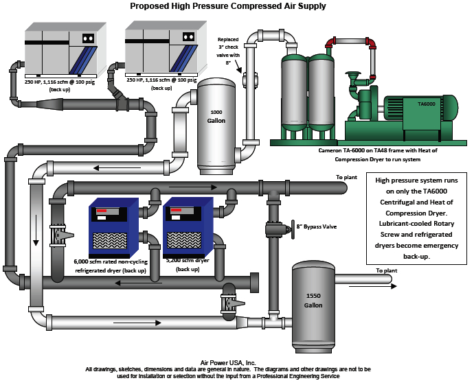
The major savings, in this project, were found in the reconfiguration of the supply-side high-pressure system (at 100 psig) and in the distribution system. A centrifugal air compressor was upgraded to a modern, more energy-efficient centrifugal air compressor installed with a heat-of-compression desiccant air dryer.
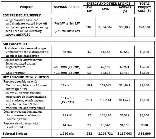
For this article, we will detail the air-flow reduction projects identified at this plant. The projects included re-piping the system, air treatment product modifications or changes, and several demand-side actions. This portion of the system assessment yielded energy savings of \$137,003 with project costs of only \$35,600.
Current System Background
This plant runs three bottle IS machines and lines of production with one furnace. As in most glass container facilities, there are two air systems – low pressure 55-60 psig and high pressure 90-100 psig. Most high-pressure air is used for controls, instruments and cold end material handling and packaging. The low-pressure air primarily supplies the forming and cooling air for the IS machines. This plant uses high-pressure plunger cooling air.
There are no compressed air dryers in the low pressure system. The main high pressure air supply has two refrigerated dryers – 6,000-scfm rated (100 psig @ 125ºF) non-cycling dryers. Current piping appears to be bypassing a great deal of air around this dryer. There is also a heatless type desiccant, regenerative dryer for the in-house air system. There is no dryer system beyond the after-coolers for the low pressure air.
Measurement
For both the high-and low-pressure systems, the following actions were taken to establish the baseline for flow and pressure.
- Temperature readings were taken on all units with an infrared surface pyrometer. These were observed and recorded to relate to the unit’s performance, load conditions and integrity. The findings were recorded on the table of compressor supply operating data that follows.
- Critical pressures including inlet and discharge were measured with a single Ashcroft digital calibrated test gauge with an extremely high degree of repeatability. Findings were also recorded in the table of appropriate compressor supply operating data.
- All low-voltage (480V) units had the input kW measured with a Fluke motor analyzer. The high-voltage units power draw was estimated by observing volt and amps, operation, and comparing to the OEM engineering specifications.
- Flow was also measured and logged from the compressor room with an Eldridge thermal mass heater wire-type flow meter and logged with an MDL multi-line unit. Readings were taken every 15 seconds and averaged.
- The same basic measurement and logging activity was carried out for system pressure using an Ashcroft pressure transducer and the same multi-channel MDL data logger.
- Individual critical pressures were taken with a single Ashcroft digital test gauge. This gauge was calibrated to the Ashcroft pressure transducers.
Air Flow Reduction Projects
Seven projects were identified in the system assessment capable of providing reductions in required compressed air flow totaling 1,549 scfm. The projects include range from piping modifications to reduce blow-off air at the centrifugal to purge control on desiccant dryers to eliminating inappropriate uses of compressed air.
Project #1: Compressed Air Supply: Eliminate Piping “Dead-heads” and Eliminate Blow-off Air
The goal of the project is to realign the centrifugal air compressor (and other high pressure compressors) to run base load and eliminate a measured 921 scfm of blow -off (i.e., wasted) compressed air. There are a number of dead-heads and crossing tees having a significant impact on the high pressure air systems. The air turbulence, back-flows and pressure loss created by these not only force modulated controls off of full-load, when air is needed, but they also create many false signals to the capacity controls precluding proper operation. Without the elimination of these issues, no control system will run properly and respond to actual system demand. Following are the connections in question:
- Dead head between the centrifugal and the rotary screw air. The objective is to keep the centrifugal at base load / full load and trim with the XF250 as required. Re-pipe to a “Y” connection to a large header collector to one of two dryers. Install pressure regulators after the receiver – 95 psig maximum set to hold.
- Regulator sized for 6000 scfm – 95 psig in / 93 psig out
- Crossing tee connection XF250 to 8” header from XF350 to reconnect with at least half of discharge pipe 4” connected to 8” line with 30º angle entry.
- Cost estimate:
Regulator installation $8,000 Crossing tee connection $3,500 Piping change $8,500 Total $20,000
Note: The XF350’s are also tied with crossing tees to themselves and the older Centac not in use. As long as you only run one unit at a time there is no need to change these.
|
Project #1 Summary Estimated air reduction 921 scfm Electrical energy cost recoverable $107.3 cfm/yr Total electric energy cost recovery $98,847 /yr Estimated Project Cost $20,000 |
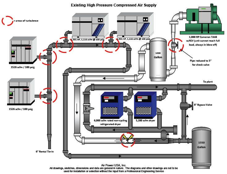
The red circles indicate the areas of high turbulence-generated back-pressure in the piping system. The compressed air flowing from the rotary screw compressors “dead-headed” to the centrifugal keeping it at constant part-load.
Project #2: Air Treatment: Add Purge Control to Desiccant Dryer and Install No-Air Loss Drains
There is a heatless desiccant dryer, rated for 260 scfm, providing a stable -40 F pressure dewpoint. The compressed air is being used for “Instrument Air” therefore the air quality is important. The unit is regenerating on fixed cycles even though there is a very low load profile. Our calculations show annual purge savings of 30 scfm with the installation of a standard dew point demand purge controller.
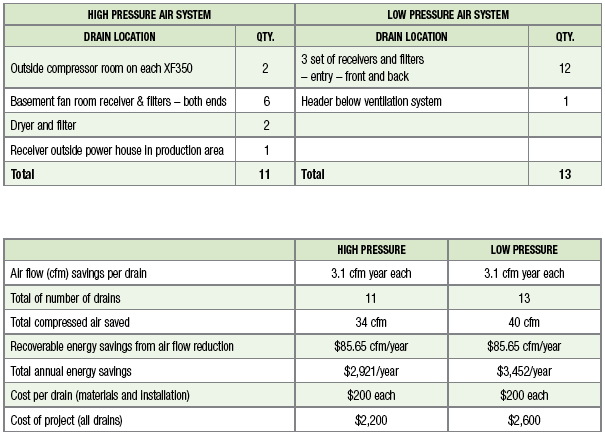
The Power House has level-activated, pneumatic-actuated no air-loss drain valves, which seem to work well and are well maintained. However, throughout the plant, there are many timer-actuated electric automatic drains that should be replaced. This project will save compressed air by replacing all timer drains throughout the supply-side and distribution system with level-activated no air-loss drains.
Dual Timer Electronic drains use an electronic timer to control the number of times per hour it opens and the duration of the opening. The theory is that the times should be adjusted to be sure that the condensate drains fully and the open time without water is minimized, because it wastes compressed air. The reality is that the cycles often don’t get reset from the original factory settings. This results in condensate build-up during the summer and in getting set wide open and not closed down later during in cooler weather. When they fail “stuck open”, they blow at a full flow rate of about 100 cfm.
Consider, for example, that the usual “factory setting” is 10 minutes with a 20-second duration. Some 1500 scfm of compressed air will generate about 63 gallons of condensate a day in average weather or 2.63 gallons per hour. Each 10-minute cycle will have 0.44 gallons to discharge. This will blow through a ¼-inch valve at 100 psig in approximately 1.37 seconds. Compressed air will then blow for 18.63 seconds each cycle, 6 cycles a minute, which will total 111.78 seconds per hour of flow or 1.86 minutes per hour of flow. A 1/8-inch valve will pass about 100 cfm. The total flow will be 100 x 1.86 = 186 cubic feet per hour, or 186 * 60 minutes = 3.1 cu ft/min on average. This 3.1 cfm would translate into an energy cost of \$300 per year based on a typical air flow cost of \$100 per cfm year.
Project #3: Replace Open Blows with Venturis
Plants with many 1/8 and 1/4 inch lines running as blow off on units will use approximately 10 and 25 cfm each, respectively, at 60 psig. One savings approach is to use an air amplifier, which requires less compressed air. Air amplifiers use “Venturi” action to pull in significant amounts of ambient air and mixing it directly into the air stream, which amplifies the air available at point of use. Air amplifiers have amplification ratios up to 25:1. Ten cfm of compressed air can supply up to 250 cfm of blow-off air to the process and generate a savings of a 15 cfm of compressed air per ¼-inch blow off. Savings may be available using 1/8-inch lines, but the cost effectiveness will not be as great. In general, the open blows are very well controlled at this plant with air used for kickers (rejects) limited to a controlled pulse and blower air at many locations including the squeezers as listed below.
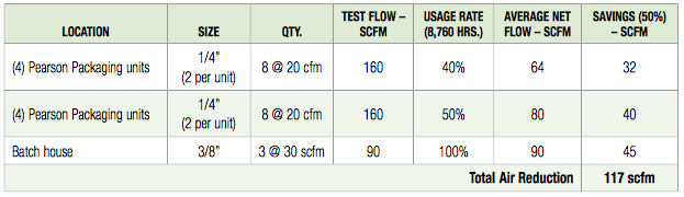
|
Project #3 Summary Estimated air reduction 117 scfm Electrical energy cost recoverable \$85.65 /cfm Total electric energy cost recovery \$10,021 /yr Estimated Project Cost $1,000 |
Project #4: Replace Vacuum Generators with Central Vacuum
Single-stage vacuum generators use compressed air by accelerating the air through the restrictor tube to create a Venturi effect to evacuate the required volume of air. These single-stage Venturi generators are somewhat limited in their ability to fit many applications efficiently, since their basic design is set to accommodate either the highest flow or highest volume requirement. Typically, this type of vacuum generator has a ratio of compressed air consumption (scfm) to vacuum flow (the rate at which atmospheric pressure is removed from a system) of no better than 1:1 and sometimes as high as 2:1 or 3:1.
Multi-stage vacuum generators were developed to improve this efficiency for many applications. The multi-stage units use a series of ejectors and nozzles that allow compressed air to expand in controlled stages. This usually improves the ratio of compressed air consumption to vacuum flow to a level of about 1:3. Multi-stage units are also significantly quieter.
Vacuum generators are very convenient and very responsive, but less efficient compared to positive displacement pumps (e.g., rotary screw, vane, or reciprocating pumps), which are the better choice when conditions require large flow, but offer potentially slower response time.
The plant’s current production system has vacuum generators at the following locations. These can be removed by tapping into the central vacuum system. The centralized vacuum system now serves the IS units and the palletizers. They only appear to be running at 50% load. Adding an additional 40 cfm and 80 cfm demand will not affect this much and may actually help the vacuum pumps run more efficiently. Install appropriate surge tanks on the Pearson packaging units #6-8 and connect them to the overhead vacuum system.
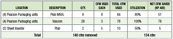
|
Project #4 Summary Estimated air reduction 134 scfm Electrical energy cost recoverable $85.65 /cfm Total electric energy cost recovery $11,477 /yr Estimated Project Cost $2,000 Connect Air Inserters to Vacuum System net Savings 12 kW Estimated Annual Savings $6,517 Estimated Project Cost $2,000 |
Project #5: Replace Air Vibrators with Electric
Air vibrators are used to keep product or packaging moving or separated – e.g., keeping lids separated prior to sealing. If a plant employs air vibrators that use about 10 cfm each, they will require about 2.5 hp or more to produce the same as a similar electric vibrator, which might use about 0.25-hp input energy. A list of potential air vibrator retrofits (with electric units) is provided below.
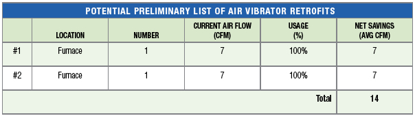
|
Project #5 Summary Estimated air reduction 14 scfm Electrical energy cost recoverable \$85.65 /cfm Estimated Project Cost $800 |
For more information please contact Hank Van Ormer, Air Power USA, tel: 740-862-4112, hank@airpowerusainc.com, www.airpowerusainc.com.