Much attention and expense is often directed towards optimizing compressor control, clean-up equipment, system pressure / flow control and main system piping in an attempt to maintain adequate and stable pressure at the end use. Often forgotten are the components of the distribution system between the main system header and the end use.
Tom Taranto, an Advanced Level 2 Compressed Air Challenge instructor uses the phrase “The Dirty Thirty” to help his students in Compressed Air Challenge’s Fundamentals and Advanced Seminars remember the importance of addressing end use pressure differential. We asked Tom for his insights on this subject:
What is the “Dirty Thirty”?
That last bit of compressed air piping connecting the end use pneumatic equipment to the compressed air header is a part of the compressed air system that I fondly refer to as the “last dirty thirty”. The reason is that it’s typically a distance of about 30 feet and the innovative/creative piping designs and installation methods are truly amazing. That last bit of piping installation is usually done with the pressure to get things running quickly and as a result is made up with the available pipe, hose, tubing, fittings, hose clamps, plastic tubing, shut-off valves, filter / regulator / lubricator (FRL) assemblies, and whatever else it takes to get compressed air connected to the machine. Since components are selected based on what’s available, little consideration is given to the average air demand and peak airflow rate used by the equipment. Of course we can’t forget about the “add-ons” for a little compressed air to run this or that.
How often have you seen problems at the end use and what is the most common problem?
Excessive restriction to compressed air flow results in equipment being starved for air supply, adversely affecting the equipment’s performance. Casual investigation and anecdotal information can lead to the conclusion that “we need higher pressure”.
What are people most surprised by?
There is often a 30, 40, 50 psi pressure drop, or more, in the last dirty thirty of compressed air piping. If there is a pressure problem with a piece of equipment, and it is several hundred feet back to the compressor room, it could be reasonable to assume that there must be a significant pressure loss in the long distance. It is surprising when the pressure drop at the last dirty thirty is 10 or 20 times the pressure loss in the long pipe all the way back to the compressor room.
 What’s a quick way to check for pressure drop problems?
A quick way to check if you have a problem at the far end is to install pressure gauges as close as possible to the end use tool, pneumatic cylinder, air motor, or whatever is the end productive use. The more the pressure gauge drops when the tool uses compressed air, the greater the upstream piping restriction. It’s important to know that gauges, being mechanical devices, do not respond very quickly. If the gauge shows a 5 psi dip, the actual pressure decay may be 15 or 20 psi. Consider purchasing a digital pressure gauge with the capability to capture peak and minimum pressure readings.
How do you correctly size hoses, filters, and regulators to avoid pressure drop?
When sizing hoses, connectors, and filters and regulators it is important to evaluate the dynamic use of compressed air and NOT cubic feet per minute (cfm) average air flow rate. For example, a machine is rated to use the average air flow rate of 20 cfm but it operates for 15 seconds and is idle for 45 seconds of every minute. The dynamic air flow rate is 80 cfm rate of flow during the 15 seconds that the equipment is using compressed air. Point of use piping, valves, FRL’s and all components that make up the last dirty thirty need to be sized to handle the 80 cfm peak airflow rate, not 20 cfm rate of flow.
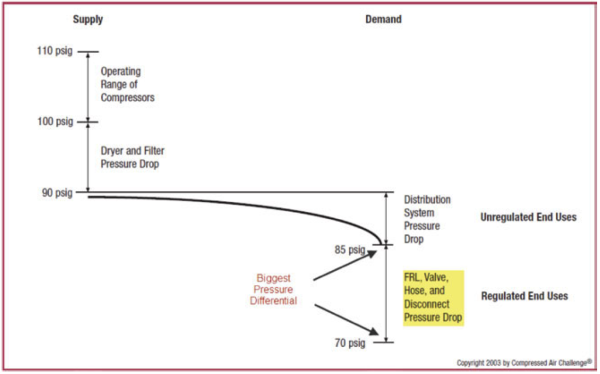
Figure 1: Typical pressure profile showing end use pressure differential
Effects of Pressure Differential
Excessive pressure drop at the end use will force an increase in total system pressure and lead to excessive compressor energy consumption. Minimizing differentials in all parts of the system, including the last “Dirty Thirty” is an important part of efficient operation.
 There is also another penalty for higher-than-needed pressure. Raising the compressor discharge pressure increases the demand of every unregulated usage, including leaks, open blowing, etc. Although it varies by plant, unregulated usage is commonly as high as 30 to 50 percent of air demand. For systems in the 100 psig range with 30 to 50 percent unregulated usage, a 2 psi increase in header pressure will increase energy consumption by about another 0.6 to 1.0 percent because of the additional unregulated air being consumed. The combined effect results in a total increase in energy consumption of about 1.6 to 2 percent for every 2 psi increase in discharge pressure for a system in the 100 psig range with 30 to 50 percent unregulated usage.
Elevating system pressure to compensate for poor design in the last “Dirty Thirty” increases unregulated uses in the whole system, for applications without regulators or with wide open regulators. The added demand at elevated pressure is termed “artificial demand,” and substantially increases energy consumption. Instead of increasing the compressor discharge pressure, or adding additional compressor capacity, alternative solutions should be sought, such as reduced pressure drop with optimized component selection. Equipment should be specified and operated at the lowest efficient operating pressure.
In the distribution system, as shown in Figure 1, the highest pressure drops are usually found at the points-of- use, including undersized or leaking hoses, tubes, disconnects, filters, regulators and lubricators (FRLs). The maximum pressure drop from the supply side to the points-of-use will occur when the compressed air flow rate and temperature are highest. System components should be selected based upon these conditions and the manufacturer of each component should be requested to supply pressure drop information under these conditions.
A Real Life Example
A printing company had installed a new machine designed to collate pages to help automate the assembly of a coil-bound book line they were publishing for a major customer. Orders were placed on an as-needed basis and could not experience delay.
Installation of the machine was done on a priority basis during a quick weekend production shut-down. Immediately upon on installation of the machine the production of books experienced problems that were diagnosed as low pressure issues. The plant was previously running at a pressure/flow control setting of 100 psi, but now the pressure / flow controller had to be bypassed and the plant pressure turned up to as high as the compressor rating would allow. Even with this, some pressure issues continued on occasion as if at random.
A compressed air auditor was called in to investigate. On examination of the supply system to the machine, it was discovered that a 15-foot section of ¼ rubber hose was being used to feed the machine. During installation, there was not enough time to hard pipe the machine into the main piping drop and since the plant used standard ¼ inch hose, this was used instead. Plant personnel, in their haste, had not realized the consequences of installing this type of supply feed. The following table shows the resulting pressure differential of 15 feet of ¼ inch hose at the collator’s peak flow of 20 cfm, which was confirmed by pressure measurement. Pressure differential across two additional quick couplers further reduced the pressure the machine was actually receiving to a level far below what was required for acceptable operation.
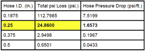
Table 1: Pressure differential of various sized hoses (15 feet at 20 scfm): Source: www.gates.com
It should be noted that if the next size larger hose of 3/8 inch would have been used, a reduction in pressure differential of about 22 psi or 88% would have resulted.
For more information visit the Compressed Air Challenge® website or contact Ron Marshall, Marshall Compressed Air Consulting, tel: 204-806-2085, email: ronm@mts.net.