During an energy audit of a facility in the upper midwest, we were asked to investigate an air compressor failure and a brief plant production curtailment issue that ended-up requiring a little of our ingenuity to resolve.
Introduction
The plant operating schedule was normally two shifts of production six days per week. They also conducted process cleaning and maintenance work on third shift and Sundays. Air compressor issues were the least of their utility systems challenges. Lighting, HVAC, and the Boilers were our main objectives, which resulted in several new opportunities for Energy/Sustainability improvements. However, the Engineering Leader had also asked us to investigate the recent compressed air system incident that they were not yet able to unravel.
The facility had two compressor rooms on opposite sides of the manufacturing building, each with two 50 horsepower air-cooled rotary screw units that were fairly new and generally in good condition. Normally one unit ran in each mechanical room and the second unit was in "auto" standby as emergency back-up. Compressor controls were working well and system-wide pressure was within our normal guidelines. Monthly the units were switched from ‘lead-lag’ for long-term equipment reliability. Hey, a fairly good air compressor system design and operating protocol was in place!
Incident Description
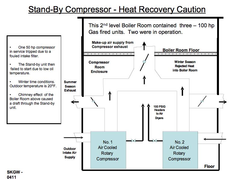
Several days prior to our visit, during a cold winter evening, the lead air compressor in one mechanical room tripped off (apparently due to a fouled intake filter and low air flow through the machine). A crucial situation then developed: The ‘standby’ unit did not start. Maintenance folks had to be called in to get a compressor running. That delay caused low plant air pressure, production curtailment and some defective product. They had yet to determine the conditions that caused the ‘no-start’.
Our first order of business was a physical assessment of the equipment. This particular mechanical room (where the incident occurred) was on the ground floor level directly below a boiler room that contained three - 100 hp gas fired, package boilers producing 70 psig steam for product sterilization and for autoclaves to clean material-handling fixtures and holders.
A heat recovery system had been part of a recent utilities energy improvement project. Exhaust air from the first-floor compressor room was being diverted up into the boiler room for warm make-up air during the winter season. KUDOS! This project is a ‘double-edged’ sword for energy savings. Every 40ºF increase in combustion air temperature to a boiler increases fuel efficiency by 1.0 %. The 180ºF exhaust air from the compressor was providing about 125,000 Btuh of ‘free” warm air into the boiler room. Moreover, the compressors had ‘outside’ air intake directly to their enclosures. For compressors, every 10ºF reduction of intake air temperature reduces motor power consumption by 1.0 %. During wintertime, compressors are more efficient with outdoor air.
Fresh air supply ducts for each unit extended about five feet to the adjacent outside wall. The exhaust heat recovery ducts were combined into a single larger duct that went up through the floor of the boiler room above. In summer, the hot air from the compressors could be diverted outside. There are three motor–operated exhaust air dampers connected to the ‘micro-processor’ control system for the compressors. One damper at each compressor exhausts the hot air outdoors for summer mode. The third (isolation) damper was in the common duct going to the Boiler Room. We asked the maintenance guys to manually actuate the dampers as part of our review. This equipment was fairly new and appeared to be in good operating condition. All of the dampers opened and sealed tight at closure. They were apparently not the problem.
Continued Investigation
Later discussion with the 3rd shift maintenance attendant revealed that the ‘standby’ compressor may have failed to start due to "low oil temperature". How could this be, since the compressor room walls were well insulated and the room ambient temperature was above 60ºF? Air supply to the operating compressor was ducted in from outside and the ducts were all insulated. Warm air piping, the receiver and the air dryer were heating the room.
We scrutinized the ductwork for the compressor heat recovery system that had been installed as part of the energy recovery job. Discharge air from each compressor cabinet went up to a common T-shaped plenum (four feet square) then up into the boiler room. That common duct contained the diversion damper for summer mode operation. The summer exhaust ducts to outdoors for the compressors were connected just above each compressor housing outlet opening (and before the combined plenum section). Refer to the schematic pictorial layout.
Problem Identification
Alas! A cause for the compressor "failure to start" was developed using a rudimentary ‘problem-analysis’ exercise. Warm air from the operating compressor was possibly creating a slight ‘chimney’ effect in the heat recovery duct to the boiler room (which was also warm and in a negative draft condition). The operating compressor also had fouled intake filters which resulted in less air flow through the machine at the time of the incident. There may have been some ‘icing’ condition on the filters due to a cold, humid air supply, which can happen on occasion. Since the ‘standby’ compressor did not include an isolation damper in the supply air duct, cold ‘outside’ air was being pulled through the compressor housing and up into the boiler room through the large (two compressor sized ) common heat recovery duct.
With a 20ºF outdoor ambient and two boilers in operation, the standby compressor could be very cold (inside the cabinet). Opening the cabinet doors quickly confirmed our suspicion about cold air being pulled through either unit when in the ‘standby’ mode. It was then that the maintenance technician said that he had wondered why the water drain trap on the ‘standby’ unit was frequently frozen-up. He had not shared the observation. We checked: Sure enough! That confirmed our theory.
Solution
There were a couple of solutions to the condition.
- Install a temperature controlled heating system on each compressor for wintertime use while in ‘standby’ mode. This option would require design modifications by the compressor service company and would also use some energy. Heat tracing of the drain trap would also be needed. Yet, this would not eliminate the cold air infiltration ‘draft’ condition.
- Install electric motor driven isolation dampers in the supply air duct for each compressor. This option introduces additional air-intake suction pressure loss conditions for the compressors if not sized to compensate. Since the compressors were not being operated at near full load, that appeared to be a more practical and less expensive option. Plant Utilities later chose this solution.
Lessons Learned
If your plant air compressor system has automatic start capability for standby units (whether centrifugal or rotary), you may want to conduct a ‘sanity check’ of the emergency start control sequence devices and installation hardware for wintertime operation. Is there a similar set of conditions waiting to happen to your system?
This was the first of three facilities at which we have encountered a ‘low-oil temperature’ situation on standby equipment. The other two were at plants where the compressors were outdoors (under a sheet metal canopy). A cold winter night had caused freezing conditions inside the cabinet of the "standby" unit, even though it had an oil heating circuit for cold "start-up". Again, the heat recovery unit (with the exhaust duct going into the adjacent manufacturing bay) was creating a cold air draft through the standby unit. One plant had two 300 horsepower rotary screw units; the other had two 150 horsepower rotary screw units. This scenario is not unique to any specific compressor model or vendor. Some newer compressor installations include a ‘no-start’ condition in the control sequence logic if ambient inside the cabinet is below 28ºF. Hopefully a "light" will alert you to that condition.
There simply is no better method for control system designers to ‘cover all of the bases’ when making equipment modifications than by conducting a thorough ‘what-if’ risk-analysis investigation and discussing the project with engineers who have extensive field experience.
For more information contact Gary Wamsley, PE, CEM, tel: 770-343-9757.