 |
One of the many tasks in assessing a compressed air system supply side is to analyze the air treatment system for appropriateness and efficiency. Most compressed air systems have one or more air dryers in place to remove the water vapor contained in the compressed air produced by the system air compressors. If there is no air dryer, the normally hot saturated air produced by the air compressors will cool in downstream system components, and condensed water will form in pressurized system pipework. This water may contaminate downstream air-powered tools and production machinery with rust, oil and pipe debris. Refrigerated style dryers are typically used in industrial plants to process general industrial compressed air that would be use by tools and pneumatic machinery. There are different modes of operation for refrigerated dryers that have different energy implications, especially when the dryers are subject to partial heat and moisture loading. In order to make a good choice in terms of energy efficiency, the purchaser should take care in understanding the operating characteristics of the different refrigerated dryer options available.
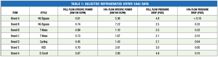
Air compressors consume the majority of the power required by a compressed air system; a well running system requiring between 18 and 22 kW of energy input per 100 scfm of air produced at a compressor discharge pressure of about 100 psig (kW/100 cfm is called specific power). Fully loaded refrigerated air dryer specific power levels range between 0.6 and 0.8 kW per 100 scfm, or about 3 to 4% of the total system power.
Like air compressors, when dryers run at partial loading, the specific power of a dryer increases, reducing the efficiency of the treatment system. This effect can be seen if the CAGI data is analyzed for a given size of air dryer. For example, a 1000 scfm unit using a hot gas bypass system to control its drying capacity might start off at a specific power of 0.7 kW/100 scfm, but have its specific power fall to 5.36 kW/100 scfm at 10% loading. A thermal mass style of dryer, on the other hand, may start out at 0.73 kW and have a less pronounce efficiency decrease at lighter loads, with a final specific power of 1.67 kW/100 scfm at 10% loading.
Example Savings Calculation
Consider a system with two 500 scfm, 100 psig rated air compressors, one spare and one backup, arranged using a single 1000 cfm air dryer. The system was sized for future capacity. Average flow produced by the running compressor is 225 scfm with peaks to 425 scfm. A variable speed air compressor was chosen to optimize the efficiency of the system at part load. The rating of the compressor at part load is 20.3 kW per 100 scfm as per the CAGI sheets. Power consumption of the compressor would be 45.7 kW. If a non-cycling air dryer is selected, the dryer consumption at the average 22.5% of rated flow conditions would be about 81% of full load, or 4.94 kW. This equates to 11% of the compressor power. If a digital scroll, thermal mass or cycling dryer was chosen, the dryer power would reduce to levels accounting for only 2 to 4% of the air compressor power.
Additional savings due to lower inlet temperature
Often in temperate climates, especially in winter months, or where air compressors are cooled with a cold water supply, the inlet temperature to the air dryer is significantly less than rated conditions. Consider a dryer that is seeing full flow, but its inlet air is only 80 degrees F rather than 100 degrees F. This reduction in temperature and moisture content will reduce the heat load on the air dryer by 38% causing the energy consumption of the dryer to fall in the same manner as a 38% reduction of flow.
Pressure differential savings
The pressure differential across the air dryer has an effect on the power consumed by the air compressor. For a given desired plant pressure, the compressors must be set at a higher discharge pressure to compensate for pressure loss. At 100 psig, air compressors consume about 1% more for every 2 psig in increased discharge pressure. For example, at full flow a pressure differential of 2.1 psid rather than 4.8 psid would cause the air compressors to consume about 1.3% less. This savings relationship does not hold true for partial loading because the pressure differential across the dryer varies with the square of the flow. For the previous example of a dryer at 22.5% rated flow the difference in resulting pressure differential would be reduced to negligible (0.1 psid vs .24 psid).
The pressure differential across air dryers and associated filters can greatly affect the operation of load/unload compressors if the majority of system storage is on the down steam side of the dryer. For example, for a system with system storage of 5 gallons per cfm capacity and a compressor load/unload pressure band of 10 psi, a 4.8 psid dryer differential plus a 3 psid filter differential would result in an effective storage equivalent of 1.1 gallons per cfm. This would increase the compressor cycle frequency by over 4 times that of a 5 gallon per cfm effective storage value. Increased cycle frequency will cause reduced compressor efficiency. For a 100 horsepower load / unload compressor running at 45% capacity, this would increase power consumption by about 18%.
Other Dryer Savings Measures
- Ambient dewpoint tracking – the dryer control adjusts the dewpoint of the processed air to a set differential from ambient.
- Timer shutdown – Shuts down the operation of the dryer on a time schedule during periods where no production is running in the plant and the air compressors are off.
- Low flow shutdown – the dryer refrigeration system is shut down when zero flow conditions exist.
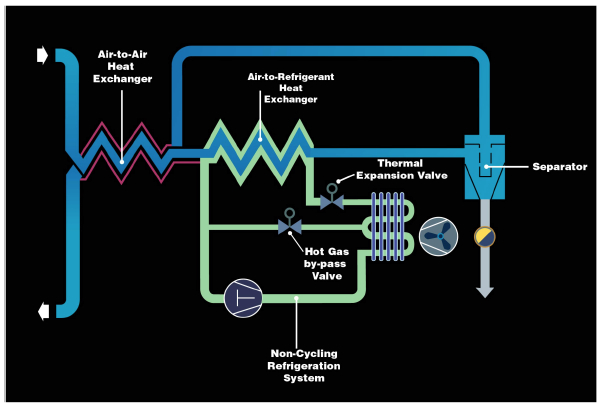
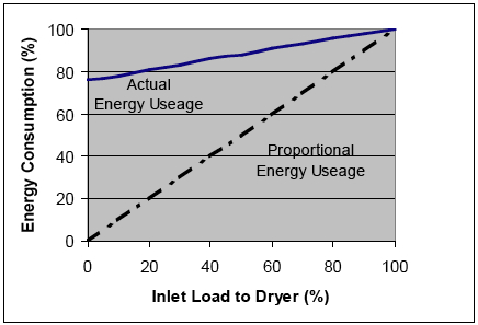
Refrigerated Dryers Styles ExplainedRefrigerated compressed air dryers have been used for many years as a cost effective and energy efficient solution for eliminating moisture from compressed air systems. These 39 ºF (3 ºC) to 45 ˚F (7 ˚C) pressure dew point machines are well-established and industry proven. Most designs operate the refrigeration compressor continuously and are termed “non-cycling”, utilizing a hot gas bypass valve to redirect refrigerant around the expansion device and into the suction line at less than full load conditions. See Figure 1. When designed correctly, these machines offer stable outlet pressure dew points and long refrigeration compressor reliability. Regardless of the air load coming into the dryer, the energy consumption is nearly the same as the full load (rated) value. This is illustrated in Figure 2.
|
|
|
Figure 1. Non-Cycling Refrigerated Dryer. Source: SPX
Figure 2. Energy Consumption in a Non-Cycling Refrigerated Dryer. Source: SPX |
As the demand for energy efficient equipment continues to grow, refrigerated dryer manufacturers are being challenged to provide “load matching” equipment that will consume less energy as the incoming load to the dryer is reduced. Three styles of energy saving refrigerated dryers are currently available: the thermal mass cycling, the variable speed and digital scroll style dryer. These designs offer some level of energy savings when compared to the non-cycling units. However, each has varying performance characteristics.
Cycling Dryers
The most common type of energy saving refrigerated dryer marketed today is the thermal mass, or cycling dryer. In this design, a thermal storage medium, either a liquid or a solid, is used to store cooling capacity whenever the inlet conditions to the dryer are less than the full load conditions. The excess refrigeration capacity that is not needed to cool the compressed air is used to cool the storage medium. Once the mass has been chilled to a pre-determined temperature, a thermal switch turns the refrigeration compressor off. The air is now dried solely by the thermal medium. After this material warms up, the thermal switch activates and restarts the refrigeration compressor.
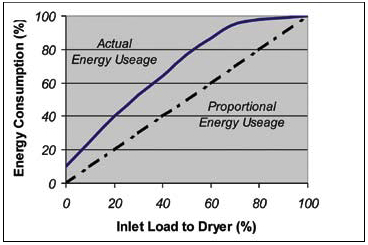
Care must be taken to design enough storage capacity so as to limit the start/stop events of the compressor to no more than eight (8) per hour, as recommended by the compressor manufacturer. Cycling the compressor more than this can limit its life and reliability. For larger dryers, the required amount of storage medium is substantial, resulting in larger and heavier dryers. Cycling dryers may show a typical dew point swing because the refrigeration system is turned on and off within a set temperature band chosen to limit the refrigeration compressor starts and stops yet keep the dewpoint of the output air at acceptable levels. Thermal mass dryers may lack the ability to closely match the actual heat load placed on the dryer with the actual energy consumed by the machine. Test results show that many thermal mass dryers will not begin to cycle until the load on the dryer reaches 75% or less than its rated capacity. Figure 3 displays measured values for energy consumption in a typical cycling dryer.
 |
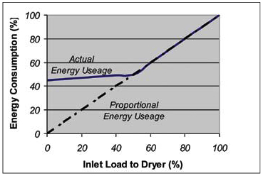 |
Figure 3. Energy Consumption in a Thermal Mass Refrigerated Dryer. Source: SPX |
Figure 4. Energy Consumption in a Variable Speed Refrigerated Dryer. Source: SPX |
Variable Speed Dryers
Another entry into the energy savings dryer market is the variable speed refrigerated dryer. This design capitalizes on the recent advances in power conditioning technology to apply newer, cost-effective variable frequency drives to traditional refrigerated dryers. These drives raise and lower the frequency of the electrical power to the refrigeration compressor in order to increase and decrease the speed of the compressor motor. By changing the speed, the refrigeration capacity of the compressor is altered in direct proportion. This is done in order to match the cooling requirements of the incoming air. By decreasing the speed, the power consumed by the compressor is also decreased. The monitoring of the refrigeration suction pressure or the compressed air temperature provides the input to the frequency drive control.
The control of these dryers is fairly complex, with higher initial cost. Due to lubrication requirements of the refrigerant compressor, the compressor motor can only turn down to 50% of the rated capacity. Turn down ratios can be improved by using smaller compressors and over-spinning (operating at frequencies > 60 Hz) the compressor at full load conditions. The complexity of these VSD controlled units sometimes poses a challenge to refrigeration technicians who are not skilled in electronic troubleshooting.
These units show linear turndown of power consumption for the top half of their capacity, but for inlet heat loads below 50%, the VSD designs activate a typical hot gas bypass valve and the dryer behaves as a non-cycling design. See Figure 4 for energy consumption as a function of inlet load for a variable speed dryer.
The Digital Scroll Dryer
The digital scroll refrigerated dryer shows excellent load matching energy savings. The evaporator design is similar to non-cycling dryers, utilizing a direct expansion refrigerant-to-air heat exchanger, providing a thermal system that is more responsive than a cycling dryer. This evaporator is constructed so that the air temperature leaving the heat exchanger remains nearly constant as the load profiles vary, even down to a no load condition.
The system control consists of a microprocessor-based controller that computes the required changes in refrigeration capacity using a PID (proportional-plus-integral-plus-derivative) style control loop.
These dryers use a digital scroll compressor that operates by using two mating scroll cavities. One of these halves is fixed; the other half mates to the fixed cavity and orbits around it. The scroll surfaces form pockets of compression that become smaller as the gas moves from the outer edge of the scroll set towards the center discharge port. These decreasing pockets create the necessary compression. There are no valves in the compression chamber and only two moving parts.
The compressor is tolerant to the ingestion of liquid and solid debris through its ability to be “compliant” along two degrees of freedom – radially and axially. “Compliance” means that the scroll set can separate briefly in the presence of a non-compressible substance, and the liquid or solid contaminant can pass through the compressor. The set then moves back to its original position and resumes the compression process. Compliance increases the durability of the compressor dramatically.
It is the axial compliance portion of the design that allows these compressors to be digitally modulated. By separating the scroll halves axially on demand, the compression of the gas can be interrupted on demand. The axial separation of the scroll halves is achieved by relieving the pressure on top of the fixed scroll half and porting it to the suction line through a small solenoid. When the solenoid is energized, the gas escapes and separates the scroll set. Once the gas compression is stopped, the flow of refrigerant from the compressor is also stopped; no work is done on the refrigerant and there is no refrigeration capacity in the system. Thus, the term digital refers to the system either having full capacity or no capacity.
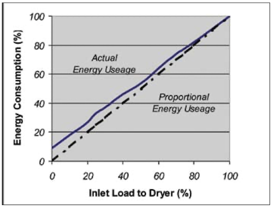
Figure 6. Energy Consumption in a Digital Scroll Refrigerated Dryer. Source: SPX
When the compressor is unloaded (no refrigeration capacity), there is no shaft work being performed by the motor. The motor, however, does continue to rotate at its normal speed. The “unloaded” motor consumes some electrical power, approximately 10% of its fully loaded value, but the constant rotation of the motor shaft assures that the oil lubrication required by the internal bearing surfaces is adequately and continuously supplied.
Since the power consumed by the compressor is reduced significantly during periods of unloading, the average power consumed by the dryer can be reduced proportionately to match the load. See Figure 6.
Testing has shown that the system is capable of maintaining very stable dewpoint output through full range of operation rated full load down to a no load condition. The use of a hot gas bypass valve is completely eliminated, resulting in a simple refrigeration circuit. Figure 7 shows a process diagram of the Digital Scroll Dryer.
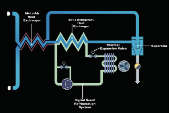
Figure 7. Digital Scroll Refrigerated Dryer. Source: SPX
For more information visit the Compressed Air Challenge® website or contact Ron Marshall, Marshall Compressed Air Consulting, tel: 204-806-2085, email: ronm@mts.net.