This Midwestern prepared food company now spends \$131,011 annually on energy to operate their compressed air system. This figure will increase as electric rates are raised from their current average of 6.0 cents per kWh. The set of projects recommended below will reduce these energy costs by \$38,736 or 29%.
This plant produces frozen foods. The plant runs production five days a week with limited production on weekends. Several years ago, an unused part of the plant was expanded to produce and package a new product line. This area is fed through a single 2 ½” header running from the compressor room and over top of the production area. Many feeds and then following sub feeds come off of this straight run of header. This new production area has a significant low pressure problem at the end of the plant during particularly heavy manufacturing runs.. Due to space constraints in this article, we will focus on the demand-side system opportunities that were found to realize energy savings.
Demand-Side Projects
Please note that all the demand-side system savings, listed in this article, depend on the capacity control system effectively translating lower air use into reduced electric cost. The current system has this type of unloading controls. With today’s piping system, the controls will accomplish this goal.
The demand-side projects, described in this article, include a leak management program, replacing open blows, adding automatic controls to venturi vacuum generators, and replacing air vibrators.
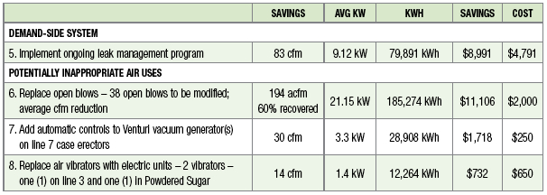
Compressed Air Leak Survey
A survey of compressed air leaks was conducted at the plant and 13 leaks were identified, quantified, located, and listed. Potential savings totaled 73 cfm for the 13 leaks that were identified. Leaks were not tagged because we had paper tags. Plant maintenance personnel were in attendance when they were located.
The plant has a continuing leak identification and repair program. The plant runs leak-checks routinely with an ultrasonic locator. This is usually implemented during 2nd and 3rd shifts. It is very important that this program continue with great intensity.
Shutting off the air supply to these leaks when the area is idle would save significant energy use. Reducing the overall system pressure would also reduce the impact of the leaks, when air to the air cannot be shut off. Repairing the leaks can save additional energy. The savings estimates associated with a leak management program are based on the unloading controls of the compressors being able to effectively translate less air flow into lower cost.
| RECOMMENDED PROJECT (#1) – Implement ongoing leak identification and repair program with ultrasonic locators. | |
| Estimated reduction of air flow with proposed project | 83 cfm |
| Recoverable savings from air flow reduction [Section 2.3] | 57.42 /cfm year |
| Annual electric cost savings with proposed project | $4,791 /year |
| Unit cost of leak repairs ($15 materials per leak and \$35 labor per leak x 13 leaks) | $650 |
| Total project cost (materials and installation) | $650 |
Best Practices EXPO & Conference Presentation VideoHow to Best Monitor & FIX Compressed Air LeaksFeaturing:
|
Leak Survey Results
|
No. |
Location/Distribution |
Est. Size |
|
1 |
Air compressor receiver air quick disconnect |
5 |
|
2 |
Line 4 Oil sprayer control – leaking regulator |
5 |
|
3 |
Line 5 under conveyor belt ahead of labeler |
5 |
|
4 |
Line 5 Case packer hole in plastic hose to cylinder (rubs on guard – correct instruction) |
5 |
|
5 |
Sauce cook – Kettle control cabinet |
6 |
|
6 |
Pesto kitchen control cabinet air-operated solenoid “blown” inside cabinet |
6 |
|
7 |
CIP No. 1 – control cabinet – air-operated solenoid “blown” inside cabinet |
6 |
|
8 |
Line 7 fitting connector to small Ballston filler |
5 |
|
9 |
Line 7 palletizer leak under stand |
7 |
|
10 |
Line 7 Dacmec lifter leak “inside” control box |
5 |
|
|
New Production Area – Has high ultrasonic background noise due to the many “blow offs” operating. These need to be shut off when looking for leaks – the high ultrasound background can “mask” many leaks. |
|
|
11 |
Line 11 Case packer Robox – cylinder rod seal on conveyor |
12 |
|
12 |
Line 10 Scale hopper filter drain (may be solenoid) |
5.7 |
|
13 |
Powdered sugar – auto jet filter diaphragm on solenoid and three (3) smaller regulators |
10 |
|
TOTAL |
83.7 acfm |
|
Replace Blowoff Air with Amplifier Nozzles
Regardless of application, there are several guidelines that should always be applied to compressed air being used for open blow off:
- Use high pressure only as a last resort
- All blow off air should be regulated
- All blow off air should be regulated to the lowest effective pressure—higher pressure means higher flow, which may not be needed
- Use Venturi air amplifier nozzles whenever and wherever possible—this will usually reduce blow off air at least 50%, freeing up more air flow for other applications
- All blow-off air should be shut off (automatically) when not needed for production.
Plants with many 1/8 and 1/4 inch lines running as blow off on units will use approximately 10 and 25 cfm each, respectively, at 60 psig.
One savings approach is to use an air amplifier, which requires less compressed air. Air amplifiers use “Venturi” action to pull in significant amounts of ambient air and mixing it directly into the air stream, which amplifies the amount of air available at the point of use. Air amplifiers have amplification ratios up to 25:1. Using 10 cfm of compressed air can supply up to 250 cfm of blow off air to the process and generate a savings of a 15 cfm compressed air per 1/4-inch blow off. Savings may be available using 1/8-inch lines, but the cost effectiveness will not be as great.
Another method for blow off to be investigated is the use of “blower generated” low pressure air. This air is much less costly to produce on a \$/scfm basis. It is the volume of air (scfm) that creates the mass or weight of the air that performs the blow off. The pressure influences the “thrust” out to the end of the nozzles where it quickly dissipates. Often a “higher volume” or weight of air at lower thrust (pressure) improves productivity and quality of the blow off over the higher pressure version.
| RECOMMENDED PROJECT (#2) – Replace 38 open blows with air amplifiers nozzles. | |
| Total air flow reduction | 194 cfm |
| Recoverable savings from air flow reduction | $57.25 /cfm year |
| Total annual electric savings | $11,106 /year |
| Total nozzle cost (materials and installation – 38 new nozzles) | $1,330 |
List of Blowoff Locations
|
Location |
Size |
Cfm usage |
Utilization |
Avg cfm usage as applied |
Change in Utilization |
Est savings cfm nozzle |
Est savings cfm timed |
Nozzle |
Est usage cfm |
Est avg air |
||
|
1 |
Line 4 |
1/4” |
10 |
100% |
10 |
Inst demand control |
3.5 |
3 |
Fixed |
3.5 |
6.5 |
|
|
Tortellini/Dryer – There are no air blows on conveyor Line 3 & 5 sensor |
||||||||||||
|
2 |
Sauce |
1/4” |
10 |
80% |
8 |
-- |
5 |
-- |
Fixed |
5 |
5 |
|
|
Conveyor – Blows caps down ¼ tube / also 4 1/8 tubes – does have auto shut off |
||||||||||||
|
3 |
Line 7 |
1/4” |
10 |
100% |
10 |
Inst demand control |
3.5 |
3 |
Adj |
3.5 |
6.5 |
|
|
Labeler / Blow off bottom of package for imprint |
||||||||||||
|
4 |
Chub KP |
25 cfm |
24 |
100% |
24 |
Inst demand control |
|
12 |
|
12 |
12 |
|
|
Cold air gun to cool glue seal – air on when machine off |
||||||||||||
|
5 |
Line 10 |
80 |
80 |
100% |
80 |
Inst demand control |
40 |
8 |
Wedge |
32 |
48 |
|
|
8 air dispersion nozzles run all the time – replace with amplifiers and demand control – 2 black / 6 yellow |
||||||||||||
|
6 |
Line 12 |
100 |
100 |
100% |
100 |
Inst demand control |
50 |
10 |
Wedge |
40 |
60 |
|
|
14 air dispersion nozzles – Raque machine – run all the time – replace with amplifier and demand control |
||||||||||||
|
7 |
Line 11 |
90 |
90 |
90% |
90 |
Inst demand control |
45 |
9 |
Wedge |
34 |
56 |
|
|
12 air dispersion nozzles – Raque machine – run all the time – replace with demand control & amplifier nozzle |
||||||||||||
|
8 |
5, 6, & 7 |
This air is used to heat the belt and avoid freezing. It is quite conceivable with 25-to-1 amplifier that the added volume mass will heat a greater area and fewer nozzles can be used at lower flow each for even greater reduction |
||||||||||
|
TOTAL ACFM SAVED |
194 CFM |
|||||||||||
Add Automatic Controls to Vacuum Generators
In order to create a vacuum, some kind of air pump or vacuum pump is required to evacuate the volume. There are two basic approaches to accomplish this task: mechanical pumps and vacuum generators (or ejector pumps).
Vacuum generators are often selected for more localized or “point of use” vacuum applications, due to the smaller volumes they handle and their faster local response times. Manufacturers of production machinery often supply them as standard equipment. There are two basic types of ejector pumps: single-stage vacuum generators and multi-stage vacuum generators.
Single-stage vacuum generators use compressed air by accelerating the air through the restrictor tube to create a Venturi effect to evacuate the required volume of air. These single-stage Venturi generators are somewhat limited in their ability to fit many applications efficiently, since their basic design is set to accommodate either the highest flow or highest volume requirement. Typically, this type of vacuum generator has a ratio of compressed air consumption (scfm) to vacuum flow (the rate at which atmospheric pressure is removed from a system) of no better than 1:1 and sometimes as high as 2:1 or 3:1.
Multi-stage vacuum generators were developed to improve this efficiency for many applications. The multi-stage units use a series of ejectors and nozzles that allow compressed air to expand in controlled stages. This usually improves the ratio of compressed air consumption to vacuum flow to a level of up to 1:2 or more. Multi-stage units are also quieter.
In general, vacuum generators:
- Use compressed air whenever they are on
- Use less air and are more efficient when in a multi-stage configuration than they are as single-stage units under certain loads
- Need to be carefully chosen – selecting the right pump for each specific application is not always easy
- Are probably not the right approach when a large and/or continuous volume is called for
- Will waste a significant amount of compressed air when pulling a lower vacuum
- Will waste a significant amount of compressed air when pulling a vacuum at any time it is not required for production
- May be less economical than a “central mechanical” pump when there are a significant number of vacuum generators used in a single area
Vacuum generators are very convenient and very responsive, but less efficient compared to positive displacement pumps (e.g., larger rotary screw, vane, or reciprocating pumps), which are the better choice when conditions require large flow, but offer potentially slower response time.
Energy cost escalates as the vacuum flow goes down with Venturi generators, so it is very important to only run a Venturi vacuum generator at the minimum vacuum flow, minimum acceptable “on time” cycle, and at the lowest effective pressure. Properly applied, Venturi generators can be very power efficient and can enhance productivity.
If there is a large central vacuum system already in place and running with excess capacity, tying the vacuum generators requirement to it will probably generate energy savings.
Current Application
There are compressed air vacuum generators throughout the plant. The majority are used in packaging, palletizing, case erection, etc. Most of the vacuum generators were set to shut off automatically when production was off. One exception was on Line 7 case erectors with three (3) PIAB M150’s were running all the time, even though the machine was not operating.
These use about 10 cfm each and, if auto controlled, would only run 50% of the time.
| RECOMMENDED PROJECT (#3) – Add automatic controls to Venturi vacuum generator on M150’s at Line 7 case erectors. | |
| Estimated flow of Venturi vacuum without auto shut off | 60 cfm |
| Total air flow in current system | 60 cfm |
| Air flow reduction with auto shut-off | 50% |
| Air flow savings with auto shut-off | 30 cfm |
| Recoverable energy savings | $57.25 /cfm year |
| Annual estimated energy savings | $1,718 /year |
| Equipment and installation cost to add automatic controls | $250 |
Air Vibrators
Air vibrators are used to keep product or packaging moving or separated – e.g., keeping lids separated prior to sealing. If a plant employs air vibrators that use about 10 cfm each, they will require about 2.5 hp or more to produce the same as a similar electric vibrator, which might use about 0.25-hp input energy.
A list of potential air vibrator retrofits is provided below.
List of Air Vibrator Retrofits
|
|
Location |
Qty |
Current Air Flow (cfm) |
Usage (%) |
Net Savings(Avg cfm) |
|
#1 |
Line 3 |
1 |
10 |
20% |
8 |
|
#2 |
Powdered Sugar |
1 |
12 |
50% |
6 |
|
TOTAL |
|
|
|
14 |
|
| RECOMMENDED PROJECT (#4) – Replace current air vibrators with electric units. | |
| Total net air savings | 14 cfm |
| Recoverable savings from air flow reduction | $57.25 /cfm year |
| Annual electric use in current applications | $801 /year |
| Unit electric demand per electric vibrator @ .25 hp | .25 kW |
| Estimated annual hours of operation for new equipment | 4,640 hours/year |
| Annual electric cost in proposed applications | $69.30 /year |
| Net annual electric savings from project | $732 /year |
| Total cost to purchase and install electric vibrators (2 units) | $650 |
Summary
Most plants can benefit from an ongoing demand-side reduction and leak management program. Generally speaking, the most effective programs are those that involve the production supervisors and operators working in concert with the maintenance personnel.
For more information please contact Hank Van Ormer, Air Power USA, tel: 740-862-4112, email: hank@airpowerusainc.com, www.airpowerusainc.com.
To read more articles about the Food Processing industry, please visit www.airbestpractices.com/industries/food.