Have you ever wondered how to stay “in control” of an engineering organization with a fixed staff and a varying workload, where the engineers all have a mind of their own? “Herding cats” is what they call it. Of course, that’s normal, right? Well, controlling multiple centrifugal air compressors is pretty close to that model, which can lead to a condition known as “control gap.” This article discusses the reasons for control gap with centrifugal air compressors and solutions to help avoid it.
Load-leveling: A Common Management Challenge
I’ve managed the total profit and loss of several engineering service teams over the years, and one of my biggest problems has been “load-leveling” to get the optimum out of every individual and the team, given our infrastructure and logistics constraints. In other words, matching fixed staff to varying loads. The telltale that you did well is the bottom line. One “KPI” is total billable revenue divided by total payroll and indirect plus direct costs. If that number is over 1.XX, you’re good. Another is everyone is pretty happy. So, having a good KPI is important. But what kills efficiency of an engineering team the fastest? Overworking of some team members and underworking of others. And having the wrong work assigned to each.
What if we looked at an individual sophisticated centrifugal air compressor with its own local controls as if it was an engineer? And the set of them as the team? When you have too many staffed versus the load, what happens in the engineering team? That depends on the mix of people, talents, experience, productivity, etc. What happens to the air compressor system? Well, that depends on the size, type, and control settings of each air compressor, doesn’t it? What if the “master controller” is just the operator telling them to run, like the manager telling them to be “at work” and letting the work randomly come in the front door.
What happens if the total capacity online or the staffing level is too high? Physics takes over, just like economics does in the team. It will only take so much of your output that month. You might work one of them to the overheating point and push the other two back to inefficient and unproductive levels. One might not know the word “no” and always is swamped. Another might have a good idea of how to act like he’s working, just to keep steady, and blow-off what he doesn’t produce. “Don’t bug me with more work – I’m swamped!” they say. That’s like the constant pressure control air compressor in blow-off. Others will try to be effective and beat themselves up. They’ll respond to their inbox or the latest crisis, crank out a deliverable in no time, then sit and spin their wheels, bugging their coworkers with questions, and being a pain in general. Then, when the next task comes, go full on and crank it out at 110% effort and do it over and over. That’s the load-unload with surge.
What Exactly is Control Gap?
Given these scenarios, how would the manager know what was really going on? Measurement at the staff level is important, coordinated with total measurement at the team. The same with the compressed air system. How would she fix the problem? First, figure out the root cause, then fix it. What is the real problem? It is the inability of one worker to pull back and ramp up enough to compensate for the variation of the team. He’s one person, doesn’t even know what the total load is, and the variation is more than him. And he can’t be just “shut on and off” all the time. When he spins his wheels, and that still doesn’t adapt to the team load, the guy in the next cube gets slowed down. The fundamental reason he can’t match load is no different than a centrifugal compressed air system suffering from control gap.
Control gap is an effect the inability to match one air compressor’s effective and efficient flow variation to match the system’s load variation. It causes system instability and inefficiency. It is caused by air compressor size and turn-down challenges, combined with the wrong control algorithm and setting. It’s the mismatch of people to load variance, and the wrong management methods to balance load.
Specific control gap problems in centrifugal compressed air systems include:
- Staying out of blow-off in a multiple centrifugal compressed air system with varying load, when load varies more than the upper throttle range of one air compressor.
- Avoiding instability and surge when trying to adapt to varying load with only one centrifugal air compressor in a set at a time.
- Attempting to parallel modulate, or “load-share” a set of centrifugal air compressors.
In summary, the problem is to match the system variation (in change of flow) to an efficient and stable air compressor set in all load ranges. The “control gaps” are the flow ranges where a good match is not found, and either instability or blow-off occurs.
Compressed Air System Examined
Let’s look at an example centrifugal compressed air system to illustrate how and when control gap occurs.
Suppose you have four, 3,600 scfm air compressors, and demand shifts between 10,000 scfm (2.8X each compressor’s capacity) to 12,000 (3.3X each compressor’s capacity). See Figure 1. With local controls, you can control the system in one of two ways. Either in “cascade” control, with the last unit on taking part-load, or “load-shared” with all units parallel modulating at about the same pressure. In reality, the latter is almost impossible to accomplish with local controls only. But even if possible, the system part-load swing is the upper modulation range of the trim air compressor(s). In cascade control, it is about 30% of one air compressor, a 1,080 scfm range. That gives a very narrow ranges for efficient turndown, from 9,720 to 10,800 scfm or 13,320 to 14,400 scfm. In parallel modulation, the optimal turndown of the set is 30% of the total, a much larger 4,320 scfm range. If combined modulation was possible, it would allow the system to vary from 10,080 to 14,400 scfm and be fairly efficient as shown in Figure 1.
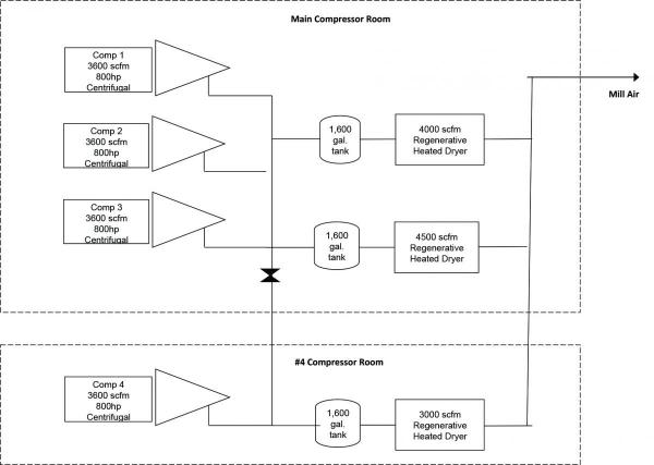
Figure 1: System before improvements.
The system flow variation is pretty much within the turndown range in load-sharing, but in the bad area where blow-off has to occur in cascade control. The mismatching of the available efficient turndown on inlet guide vane (IGV) modulation and the actual system variation is control gap. If cascade control is used and the centrifugal trim air compressor was put into “auto dual” control (upper range modulation and unloading), it would cycle excessively. So that is avoided by controlling with “constant pressure” (upper range modulation and lower range blow-off) control, and blow-off happens.
Initially, three of the four air compressors were operating in parallel, feeding two parallel regenerative dryers, with local constant pressure points. They were sharing the load fairly well. There was minimal blow-off (less than 10%). The fourth air compressor was isolated to its dryer and blowing off a bit more. Total waste was about \$50,000 per year. Expensive control panel retrofits were done, which improved local control. However, they staged the three air compressors (“cascaded” the setpoints). This full-loaded the first two air compressors but caused the third (isolated still) to cycle and surge. Waste was now \$80,000 per year. See Figure 2.
The alternative of automatically starting and stopping a centrifugal air compressor (like a screw air compressor control system - a “target sequencer”) was not considered because of air compressor size and slow start-load time. Why was more blow-off happening with modern controls? The answer is control gap. The effective and efficient ranges were limited, and not where the demand was.
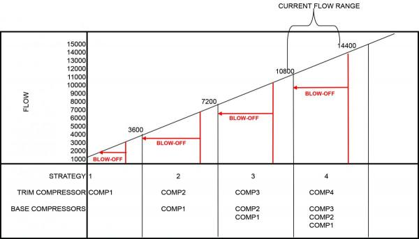
Fiure 2: Control strategies before improvements.
Unraveling the Root Causes of the Problem
The example above can be used to unravel the root causes of control gap. In this case, cascaded control settings forced one air compressor to play the “trim” role, and it could only trim in the upper 30%. Demand was in the other lower range (less than 3.1 X air compressor’s capacity), requiring the fourth air compressor to blow off. Even if the following problems were fixed, there would be significant blow-off. System demand was just barely below three air compressors 95% of the time (about 2.9 to 3.0 air compressors) but regularly jumped over three units.
Piping and dryer pressure drop, along with partial segregation of one air compressor, also made controls coordination difficult. Air compressors No. 1 and No. 2 can’t deliver full air, because the line between them and air compressor No. 4 is too small. When both air compressor No. 1 and air compressor No. load up, the pressure drop across their dryer spikes and air compressor No. 1 has to unload (and surges also). Storage is inadequate with three, 1,600 gallon receiver tanks before the dryers, including two for air compressors No. 1 through No. 3 and one for air compressor No. 4.
Now let’s look at what might happen in this actual system if demand increased from 2.9 to 3.1 air compressors and cascade control is still used:
- Assume the valve is open between air compressor No. 4 and the rest of the system, the piping is adequate, and we are merely staging the air compressors in a “cascade” manner: 94 psig, 92 psig, 90 psig, and 88 psig are the start points of the four air compressors. Their pressure control points inlet guide vanes (IGVs) are five psi over that, 99, 97, 95, and 93 psig. Blow-off Valve (BOV) setpoints to protect from surge are five psi higher, 104 down to 98 psig. In reality, minimum power protects from surge also, so it is more complicated.
- When the demand slightly exceeds the three air compressors’ capacity, say going up from 10,400 scfm to 11,000 scfm, and three air compressors were running, the IGVs would incrementally go to 100% slowly, pressure would drop to 88 psig and the fourth air compressor would start.
- The size of the receivers and the size of the air compressors create a pressure rate of change event. The pressure quickly rises because 14,400 scfm is being delivered, 3,400 scfm more than needed.
- Rate of change = air compressor capacity (scfm) / [(tank size, gal) / 7.5] X 15/60 psi/sec.
- For a 3,400 scfm event, and this system which has three, 1,600-gallon tanks, the pressure rate of change is 3,400 / [(4800/7.5] X 15/60, which is about a 1.3 psi/sec rate of change. The first part of pressurization is 3 X faster, when the pressure ahead of that air compressor’s dryer is lower than system pressure, and the dryer is acting as a check valve. Only 1,600 gallons of the storage is effective for that time.
- Proportional and integral settings on the IGVs are set much slower than that, so the pressure rises quicker than the trim air compressor can react and hits the BOV maximum pressure point before the IGVs can react and control pressure. Power drops slower than the surge controls can work, and the air compressor surges. The dryer dynamic pressure drop was part of the problem.
- The cycle keeps going as shown in Figure 3. The cycling of air compressor No. 1 is primarily due to control gap. The upper modulation control range is only 1,080 scfm and is less than the system flow variance. It doesn’t match either.
- The cycle keeps going and going and going …
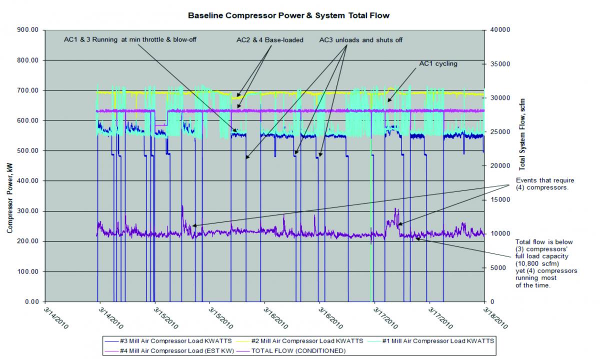
Figure 3: System operation before improvements. Click here to enlarge.
Two Solutions for Fixing Control Gap
Now that we’ve seen how and why control gap can happen and problems it creates, let’s look at options to fix it.
One option involves load-sharing controls without a new trim air compressor. This can make all the air compressors control together like a set, minimizing blow-off. See Figure 4, which describes the following steps:
1. Increase line size on wet and dry side.
2. Increase storage. Calculate storage based on tested control response that air compressors can achieve.
3. Balance dryers.
4. Add master control: Implement “load-sharing” controls – several options:
- Have local control panels integrated with a master controller that understands their distance from surge line, and parallel modulate them to be equidistant from surge.
- Use existing control panels and bump the air compressor setpoints to keep the air compressors approximately balanced in load. One method is to pick one at a time to be “trim.” When it gets to minimum IGV position (at the surge offset) and load is dropping, shift trim to the next air compressor, and modulate it to minimum, and then the third, and then the fourth unit. Attempting to change all four to balance at the same time would probably be unstable.
5. When all running air compressors are at the minimum load position and below a flow threshold you know can be delivered by three air compressors for a period of time, one air compressor can be unloaded. Since storage is enough and air compressor response time is fast enough, the remaining air compressors open up and pressure is maintained. Then that air compressor can shut off after its unloaded timer expires.
The advantage of this solution is that it offers a lower cost than adding trim air compressor(s). There are several disadvantages, including efficiency drops when operating close to the surge line, and at 10,000 scfm with four air compressors, the system will be right at minimum throttle. In addition, the system has no standby capability.
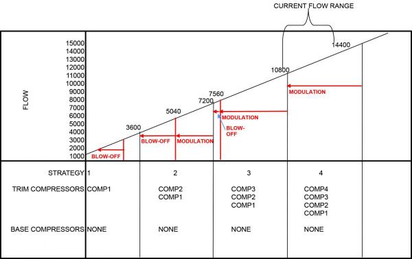
Figure 4: Control strategies after improvements, pure load-sharing.
A second option to resolve the control gap issue is to use a hybrid load-sharing and a trim air compressor. This can compensate for most of demand variance with a smaller, faster trim air compressor, and in “gaps,” load-share the centrifugal units. See Figure 5, which describes the following steps:
- Open line between all air compressors.
- Increase line size on wet and dry side.
- Increase storage.
- Add 500 horsepower (hp) load-unload screw air compressor.
- Balance dryers.
- Add master control: Implement a hybrid system, incorporating both centrifugal/screw base-trim and “load-sharing” controls. Use a third-party controller that performs one of two algorithms, depending on flow range.
- Base-trim: Base load X centrifugal air compressors and trim the screw air compressor.
- Load-sharing: To avoid “control gap” when flow is in the 70 to 100 percent of the centrifugal air compressors online, load-share the running centrifugal air compressors. When all running centrifugal air compressors are at the minimum load position, an air compressor can be unloaded. Then, the centrifugal air compressors will fully load and the screw air compressor will start and carry the difference. Then that air compressor can shut off after its unloaded timer expires.
One advantage of this method is that it’s more efficient than running all four centrifugal air compressors. The unloading losses of one smaller screw air compressor (about 20% of 500 hp less than half the time) are less than the losses for running four air compressors at minimum load (about 10% of 3,600 hp). This method also provides one back-up centrifugal air compressor. The downside of this solution is that it’s more complex and costly.
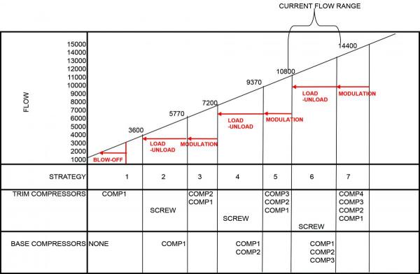
Figure 5: Control strategies after improvements, hybrid system with 500 hp trim air compressor.
One company I’m familiar with actually implemented a hybrid system and was very successful in doing so. The added benefit of having a standby centrifugal machine drove the project. A new dryer was installed also to reduce pressure differential and allow one to be shut off for maintenance at a time. The screw air compressor ended up fully loaded rather than loading and unloading. But it still worked well, eliminating control gap, saving \$100,000 per year just in electricity, and netting an incentive check of \$394,000!
A Happy Bottom Line
Avoid control gap by good management. Develop the proper master controls and system configuration to balance the air compressors with parallel modulation, or to bring in a new trim air compressor, or a hybrid of both. In any case, match the efficient and effective air compressor selections and control modes to the actual flow variances that could happen in any scenario. Costs will be minimized, and reliability maximized Your team will be happy and so will your bottom line!
For more information about this article, contact Tim Dugan, President of Compression Engineering Corporation, tel: (503) 784-2331, email: Tim.Dugan@comp-eng.com, or visit https://www.compression-engineering.com/.
To read more air compressor technology articles, please visit www.airbestpractices.com/technology/air-compressors.