Blowing a jet of compressed air at an object is a common but “poor” use of compressed air. Often the blowing nozzle is a piece of pipe on a hose with a manual valve for control. This quickly solves a production problem when a more efficient factory made nozzle is either physically too big, too expensive, or not on site when needed. Retrofitting with factory made nozzles is often ruled out by for the same reasons, and the time needed by managers and fitters to change a nozzle for often little gain in production.
A pipe nozzle can be made both more effective and more efficient by crimping the pipe 5 diameters back from its outlet. This can be done in a workshop, or to installed nozzles, without affecting the general shape of nozzle. Maintaining nozzle shape is important so that the carefully bent tubes keep blowing at “just the right spot”.
Crimping small copper tube nozzles can be done in a few minutes. Nozzles from stronger materials or that are bigger may take longer depending upon the crimp shape and the tools used.
Crimping a pipe nozzle is a quick, zero capital, technique to save compressed air.
Using crimped pipe nozzles, one site saved >90% of the compressed air used by one process and >63% by another.
Why it Works
Crimping a pipe nozzle changes the jet it creates from being low speed (sub sonic) to high speed (supersonic). The crimp creating the nozzle throat, reduces pipe area and so the fluid flow rate.
In a convergent nozzle, the pressure energy of the fluid is converted to velocity but only where the fluid is affected by a lower downstream pressure. Pressure changes move upstream in the fluid at the speed of sound (Mach 1). When the fluid speed reaches Mach 1 at the nozzle throat, no change in pressure ratio will increase the fluid speed. This is called the critical pressure ratio and for air is 1.89:1.
For the air speed to increase above Mach 1, it needs to be able to expand sideways. To allow this the nozzle walls after the throat diverge so a supersonic nozzle is also called a convergent - divergent nozzle.
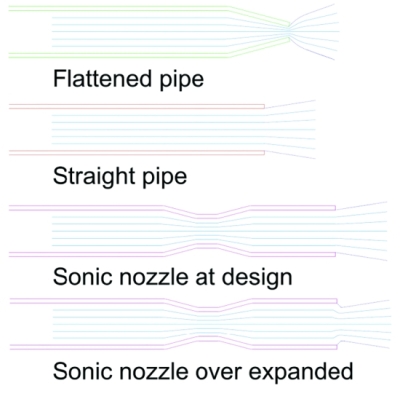
Figure 1: Flow through different nozzles.
Figure 1 shows the air flow patterns in and from different nozzle shapes. For:
- The flattened pipe nozzle the throat is at the pipe outlet. For any upstream air pressure > 13.1 psig (91 kPag) the outlet speed is Mach 1. For pressures >13.1 psig, outside the pipe the air expands sideways. The jet speed is ≤ Mach 1 and the jet has a wide angle.
- A straight pipe, the throat is an upstream restriction e.g. the fitting connecting the pipe to a hose, valve, or an elbow. The jet will have a speed of ≤ Mach 1. If the air is:
- Fully expanded before it enters the pipe, the jet angle will typically be 15 - 18°.
- Under expanded, the jet angle will be wider like the flattened pipe.
- A sonic nozzle, the throat is the small section in the middle of the nozzle:
- At its design pressure ratio. The pressure inside the pipe end is 0 psig. The jet speed is >Mach 1 with the typical angle of 15 - 18°.
- Above its design pressure ratio (no image), inside the pipe end is >0 psig. The jet speed is >Mach 1 but like the flattened pipe the air will expand sideways outside the pipe giving a bigger than typical jet angle.
- Below its design pressure ratio, the pressure inside the pipe end is <0 psig. The jet speed is >Mach 1 but narrowed by the surrounding air pressure.
These sonic nozzle jet shape descriptions are simplified. Use the internet to read more detailed ones.
What Crimp Shape to Use?
The throat shape is ideally round but creating it requires a rotary swaging tool. The throat can also be a shape with straight sides (triangle, square etc) which are easier to crimp. The number of throat sides affects the nozzle area ratio and performance, but for >3 sides this is predictable as the sum length of the nozzle sides must equal the pipe circumference.
A two sided crimp (squeezing the side of the pipe together with pliers or in a vice) can have any area ratio, but the error between “design” and “manufactured” area ratios can be large and unpredictable. A two side crimp can also lower the strength of the nozzle so should only be considered if reworking flattened end nozzle.
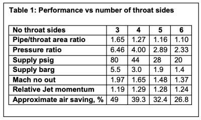
Table 1 shows the theoretical performance of different shaped crimp pipe nozzles. The “Relative Jet momentum” is the jets force compared to an open pipe at the same supply pressure.
A Case Study
The Carnot Group has a customer with a large, conical hopper feeding powder into two air slides (East and West). The flow of the powder along each air slide is controlled by a knife valve.
To prevent the powder jamming the valves, compressed air is blown against the back of each valve blade. The air nozzles are OD½” tube welded to the sides of the air slides. ID ½” air hoses connect the nozzles to a manifold. Fig 2 shows the West air slide which has a nozzle on each side of the slide (blue air hoses). The East slide only has 1 nozzle.
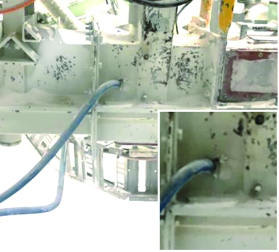
Figure 2: West air slide with close up of one of the air blows.
The hopper is fluidised above the air slides by blower supplied air. To fluidise the hopper below the air slides, there is a porous “tile” at its base supplied with compressed air. There is also an OD ½” tube lance entering from the side of the hopper that bends down internally to blow the top of the tile. In total there are 5 compressed air blow points around the hopper.
Figure 3 shows the compressed air piping supplying the blow points. For testing purposes, a flow and pressure logger was temporarily installed using valves to bypass and isolate section of the pipe.
Initial testing showed:
- A flow of 72 CFM (2.04 m3/min).
- After passing through a filter regulator, lock out valve and 2 elbows, there was only 25 psig (1.7 barg) in the pipe before any take off. The regulator was set to a much higher pressure. This pressure was measured before air was diverted through the flow meter.
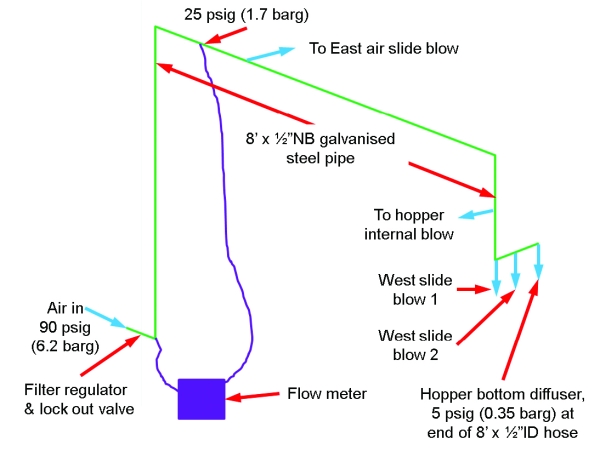
Figure 3: Hopper compressed air blows supply piping.
This loss of pressure should be no surprise. There were 5 x ½” hoses being supplied by a single ½” pipe. There was sonic expansion (pressure ratio >1.8:1) in either the regulator or isolation valve to the extent that both were tagged as leaks due to the amount of ultrasound noise being emitted.
From the logged data, the nozzle jet momentums were estimated. Engineered nozzles could not be fitted to these points, so crimp pipe nozzles were used. These were OD 3/16” copper tube with a 3 sided crimped throat as shown in Figure 4. Figure 5 shows the modified electrical lug crimp tool used to crimp the tube throats. The tube nozzles were placed inside the existing ½” tube nozzles using ¼ BSP x 1/4” tube compression and other fittings. The new internal blow nozzle was 18” long but being annealed copper tube, it was able to pass through the bend in the original ½” steel tube one.
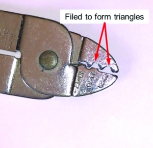
Figure 4: Tool used to crimp 3 sided throat.
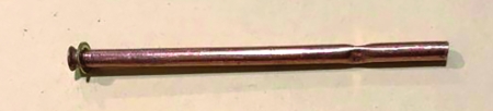
Figure 5: Crimped pipe nozzle from OD3/16” tube.
Pressure regulators were fitted to the supply to each blow point and after consultation with the plant operators were set in the range of 20-30 psig. The bottom tile had a regulator and restricting orifice fitted to control its air flow.
Follow up testing showed:
- A compressed air flow of 3.2 CFM (0.09 m3/min) a >90 % saving.
- A pipe pressure of 75 psig (5.2 barg) instead of 25 psig (1.7 barg).
On another process, 3 x 5/16” pipe nozzles were changed to 3 x 3/16” crimp pipe nozzles dropping the compressed air flow from 35 to 13 CFM (1 to 0.37 m3/min) a 63% saving.
Conclusion
Compressed air nozzles made from pipe are a quick solution to production problems. Engineered, factory made nozzles have better performance, but are often too costly and not at hand when needed. Crimping the pipe nozzle so that it becomes a sonic (convergent divergent) nozzle, can quickly provide most of the benefits of a factory made nozzle when the latter, is not practical or cost effective.
For more information please contact Murray Nottle, The Carnot Group, mnottle@carnot.com.au.
To read similar System Assessment articles visit https://www.airbestpractices.com/system-assessments.
For expert presentations, visit our Webinar Archive Section dedicated to Piping & Storage at https://www.airbestpractices.com/magazine/webinars.