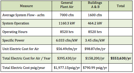
This is a corn mill processing cornstarch, sugar, and other byproducts. Ambient air is contaminated with extremely high levels of dust due to the manufacturing processes and material handling. Average electric rates at the plant are \$0.04 / kWh. The actual plant electric cost for compressed air production is \$553,630 per year.
The load profile of this compressed air system is relatively stable during all shifts. The full load operating range is 355 days a year, 24 hours a day, 8520 hours a year. There are no flow meters in the system. The system pressure appears to run from 60 to 75 psig in the headers during production for general plant compressed air and at 80-92 psig in Buildings A and B.
There are a number of measures, recommended in this review, able to reduce the electric costs to operate the compressed air system. Collectively, these potential measures total \$123,234 per year in annual energy savings. Due to article length limitations, we will highlight only a few of the measures.
Blended Power Rate: \$0.04 kWh / Hours – 8520 per year

The General Plant Compressed Air System
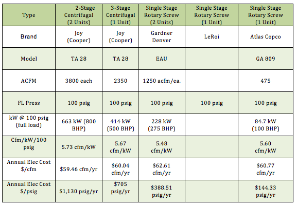
The general plant compressed air supply comes from two 800 horsepower Joy centrifugal compressors rated for 3800 acfm each at 100 psig full load pressure. This compressed air then goes to two (2) PE 4000 External Heat Reactivated desiccant compressed air dryers capable of handling 4000 scfm of air at 100°F, 100 psig inlet conditions and delivering a –40°F pressure dew point. When the dryer, drains and traps are working correctly, the plant does not have condensate or oil carryover in the production areas - according to plant personnel.
The general plant compressed air system can run on 60 psig pressure and the compressors are run at 84-85 psig to deliver various pressures to production areas. The below pressure readings were taken with local pressure gauges.
| Compressor Discharge | 84 - 85 psig |
| After Dryer / Filters | 75 - 80 psig |
| Grind I | 65 - 70 psig |
| Grind 2 | 68 - 75 psig |
| New Refinery | 65 - 68 psig |
| Bldg. 128 | 50 - 52 psig |
| BCD | 60 - 75 psig |
| Dextrin | 60 - 65 psig |
| Tear Down | 50 - 60 psig |
| Tear Down | 65 - 70 psig |
| Syrup Solids | 70 - 75 psig |
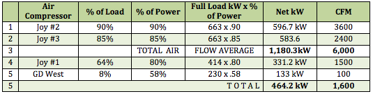
Past records indicate both 800 horsepower compressors were often at full load (amps) particularly during the summer weather. In the past, the general plant compressed air system could run with just one 800 horsepower centrifugal compressor and with a partial load on the 500 horsepower centrifugal compressor.
Buildings A & B
There are two buildings requiring higher compressed air pressure than the 60-75 psig of the general plant air system. The building A warehouse averages 85 psig pressure and the blenders in building B require a 90 psig pressure minimum.
Compressed air for these areas was originally supplied by one of two Gardner Denver 250 horsepower single-stage rotary screw compressors. Both units are lubricant-cooled and rated for 1250 cfm each at 100 psig. One of these units has problems with the variable displacement capacity control systems that needs to be repaired.
Today, these two units together cannot supply enough compressed air to run this area. The current system is supplied by a 500 horsepower Joy centrifugal in Building A rated for 2350 acfm and one Gardner Denver 250 horsepower rated for 1250 acfm. This compressed air also goes through a Pneumatech PE-1300 external heat desiccant dryer and the appropriate filters.
Observations
All of the centrifugal and rotary screw air compressors are efficient, well-applied air compressors capable of delivering the 100 psig full load pressure in a continuous manner. The units are well applied. With the exception of the one variable displacement control system, they appear to be in good operating order and well maintained.
They reflect the basic state of the art for their type of air compressor. Newer centrifugals will have some basic full load efficiency improvements (< 2% generally) and some more effective turn-down (5% better). Two-stage lubricated rotary screws will have from 7% to 10% full-load efficiency gains compared to the existing single-stage units.
If any one of the centrifugal air compressors goes down for any reason, including maintenance, the plant has no “back-up” compressed air.
A basic objective of this project is to reduce compressed air demand and then reconfigure the supply-side to optimize the efficiency, of the existing air compressors, while having back-up air compressors. The goal will be to have the general plant compressed air system run on just one 800 horsepower and one 500 horsepower centrifugal air compressor – with the other 800 horsepower centrifugal as the back-up machine. The goal for Buildings A & B is to support them with one of the Gardner Denver 250 horsepower rotary screw compressors with the second GD unit acting as back-up.

Air Compressor Controls
The two most common controls used, on centrifugal air compressors, are modulation and blow-off. Modulation is relatively efficient at very high loads, but will not work much below 80-85% load. After modulation or turn-down, the compressor then just “blows-off” and/or recirculates excess air. The basic power draw at the blow-off point then stays the same regardless of the load. There are modern electronic control systems that can be applied today that will effectively close off the inlet and will blow the unit down to idle and significantly reduce the kW draw. Inlet guide valves are available to increase the effective turn down range from 15-20% to 25-30% and increase the unloaded efficiency.
The current centrifugal air compressors have Joy Quad III and Quad 2000 Electronic Auto Dual Control and IGV’s (Inlet Guide Vanes) on the two 800 horsepower units. The 500 horsepower unit just has straight turn-down or modulation and blow-off. The units involved have capacity controls capable of translating “less air used” into a comparable reduction in electric cost.
The two most common controls used, on rotary screw air compressors, are modulation and online/offline. Modulation is relatively efficient at very high loads—and inefficient at lower loads. Online/offline controls are very efficient for loads below 60%, when properly applied with adequate time for blow-down. There are several other control types (e.g., “rotor length adjustment” or “variable displacement” and “variable speed drive”) that have very efficient turn down from 100% load to about 60% load.
The Gardner Denver rotary screw compressors, supporting Buildings A&B, use variable displacement turn valve controls. One of the units needs to have the capacity control system re-set and repaired. The unit is using 133 kW to deliver only 100 cfm of compressed air right now. This is not a difficult repair.
Reducing Compressed Air Demand
This project came up with projects reducing compressed air demand by 1,080 cfm in the general plant air system and by 480 cfm in Buildings A & B. These demand-side projects are what make it possible for the existing air compressors to be reconfigured to meet demand while now having back-up air if needed. The demand-side projects include identifying and repairing compressed air leaks, addressing inappropriate uses of compressed (like blow-off air), reducing pressure, and installing no air-loss condensate drains. Due to article length limitations, we will not provide detail on these projects in this article.
| Demand-Reduction Projects | General Plant Air | Buildings A&B |
| Leaks | 800 cfm | 250 cfm |
| Inappropriate Use | 200 cfm | 150 cfm |
| Lowest Effect Pressure | 50 cfm | 50 cfm |
| Condensate Drains | 30 cfm | 30 cfm |
| TOTAL | 1,080 cfm | 480 cfm |
Action Plan Phase 1
The below bullets were the actions items recommended to the client. These action items were implemented. We hope that readers of this article will get some ideas from these examples.
- Repair as necessary the controls on the GD 250 horsepower compressor to supply Buildings A & B. Reset controls to have the base-load unit stay on. The second machine to come on as needed. Idle and shut off when not needed.
- Repair all leaks identified already in Buildings A & B. There were many very large leaks masking small leaks.
- Go back over Buildings A & B with a leak-locating team to find the leaks passed over the first time.
- Repair and continue to identify, tag, and repair leaks in all the buildings in the general plant air system.
- Identify the restriction in flow to Buildings A & B.
- Replace prefilters with loose-packed deep bed mist eliminator to reduce pressure drops.
- Replace all timer drains and manual drains with no air-loss electric or pneumatic actuated condensate drains.
- Replace, if acceptable, vortex coolers with heat tube.
- Install venturi amplifiers on all open blows.
- Set automatic shut-off controls on all venturi vacuum generators that run full time – or replace with central vacuum system.
Piping Considerations for Phase 2
If the plant decides to build a new compressor room in the near future with the existing equipment, we have provided a suggested schematic layout drawing in our report. Some of the suggestions are detailed below.
- Install each 800 hp centrifugal with its appropriate filter (loose packed, deep bed) and dryer.
- Use 10” diameter discharge pipe or larger (use long “L’s” – not “T’s” as you have now) and ues 8” diameter discharge pipe for the 500 hp unit.
- Install a high quality shut-off valve in each line and then connect to a 18” (or larger) header running the length of the compressor room (100’ est). Thenconnect with 30° to 45° directional tie-ins. This will act as a 1300 gallon class air receiver and handle the air flow with no other pressure loss other than the filters and dryers. These can be pre-welded connections and valves for future additional compressed air flow tie-ins.
- This large header will also be an excellent point to pick up a target or set-point pressure for use with a central networking capacity control system.
- Slope the header toward the exit point from the room.
- Install a 3500 gallon vertical (150 psig) air receiver below the header. Run the main air line (12” or 14”) to the bottom section of the receiver.
- Run the distribution air line (s) from the upper half of the air receiver to individual areas or in header from (12” to 14”) to later back up in smaller sizes for various production sectors.
- Once the system is stabilized and optimized it should work very well with the existing piping.
However there are some things to consider in the near future whether you relocate the general air supply or not.
- Repipe with the back up air from the Joy #1 going directly into the air receivers.
- Tie the two receivers together with 8” pipe.
- Leave each receiver with one line to Building A and another line to Building B.
- Install one flow/pressure regulator in each line with service bypass to deliver “steady desired pressure” to each sector and eliminate system overdrive and “artificial demand”.
- Measure the flow used in Buildings A & B with accurate meters appropriately timed to identify minimum flow, average flow and peak flow. With this information, establish optimum sizing for base load and trim operations. You may find there will be significant energy savings by utilizing a smaller horse power – variable speed drive trim unit – or you may not.
Testing and Measurement
In order to maintain your system at peak efficiency, we recommend the plant obtain and use certain test and monitoring equipment.
- Compressed Air Leaks: The plant already owns two excellent leak locator instruments. We suggest you begin a on-going leak identification and repair program with full record keeping. This should be done 2-4 times a year in the beginning. After the first year of attention and repair this can usually be effectively reduced to 1 or 2 times a year.
- Flow Measurement: Long term successful compressed air management programs usually identify the cost of compressed air and make it part of each department’s overall operating cost – to do this effectively flow measurement is critical.
- It may be premature for this but we would suggest you obtain a portable flow meter able to read real time data and also log.
- Pressure Measurement: Measuring pressure with the “Same Gauge” and a gauge with a high degree of repeatability is critical to compressed air distribution analysis as you saw working with us. We use a Helicoid HG2000, 0-200 psig gauge with .25 % accuracy which cost about \$300. We recommend you use something similar.
Lubricant Selection
The plant’s air compressors are using a Food Grade lubricant which is a PAO synthetic hydrocarbon. This particular synthetic, unlike many others, does tend to “varnish” when “over run” and its ability to run long hours is very sensitive to ambient conditions and operating temperatures.
We believe, after discussion with your maintenance personnel and observing the, refilling but not changing of the oil, that you probably have “varnished compressors”. This will severely shorten the life of seals, or rings, oil filters, and air oil separator and if continued to run undetected the ultimate “locking up” of the unit endangering the motor, drive coupling etc.
There are other good synthetic lubricants that are much less sensitive and should run about one year in your environment (diester synthetics, PAG’s, non food grade PAO’s etc.). You can only use these lubricants if you feel you can have compressed air purification systems in place through filtration and drying (consistent .05 ppm is very obtainable) equipment.
Other food products companies do both – some use food grade – some don’t.
In any event, regardless of what you use you should set up a continuing oil analysis program to determine and monitor the projected oil life “without varnish” and general lubricant condition. I know of many operations running food grade lubricant today that have to change oil every 1000 hours (about every 40 + days) to avoid problems.
Reconfigured System
Blended Power Rate: .04 kWh / Hours 8520 /yr
For more information contact Hank van Ormer, Air Power USA.
To read more Air Compressor Technology articles, visit www.airbestpractices.com/technology/air-compressors.


