As readers of this publication know, there are many ways to save energy in industrial compressed air systems. One common supply side technology is the variable frequency drive (VFD) of the compressor. It is well-documented that positive-displacement compressors with VFDs provide cost-effective savings in comparison to inlet modulating, load-unload, and variable displacement control. Early in the development of VFD compressors, they were essentially “bolt-on” drives. The OEM delivered a fixed-speed compressor and installed a separate VFD to control it in the field. Most manufacturers of screw compressors now offer new packaged VFD compressors, designed with the drive integrated into the compressor’s controls. Air-end, motor, lubrication, cooling, and speed-range are optimized for VFD operation. There are definite advantages to packaged units, particularly if a new compressor is needed anyway. However, there are good reasons to retrofit some compressors with a VFD.
The goals of this article are to make the case why VFD-retrofits are sometimes a good option, recommend prerequisites for such a project, and recommend a template for a typical project. A case study at a food processing plant project will be referred to.
Reasons to Consider a VFD Retrofit Project:
- Energy savings are a priority. Without this priority, the project will not be worth it.
- A new VFD compressor is too costly. Some new VFD compressors can cost at least 50% more than conventional fixed-speed compressors. If there is not available capital, a retrofit might be justified at lower cost, and net the same savings.
- There is no room or electrical capacity for a new, large VFD compressor. New VFD compressors require higher peak current than a conventional compressor of the same nominal motor power. This is because the compressor is not at its peak efficiency at the high speed, and there are additional VFD losses that are max at top speed.
- New VFD compressors don’t always integrate well into customer’s master controls. Often, new VFD compressors are sold as stand-alone units in multiple compressor systems, and the integration issues are ignored. In cases where we attempt to integrate them, some models don’t interface well with a third-party master control and monitoring system. Some OEMs are getting better at supporting integration.
- New VFD compressors are not always as reliable as the existing fixed speed compressors. Sometimes, compromises are made with VFD packages, including smaller air-ends, proprietary motors and drives, etc. In addition, there are more points of failure, as a drive is less reliable than a starter.
- A suitable compressor for retrofit exists. See the next section.
Prerequisites Recommended for a VFD Retrofit Project:
- Correct Size and Type of Compressor is Available and in Good Condition:
- To properly integrate a VFD compressor into a multiple compressor system, the VFD compressor must have a “turn-down” (min-max speed flow range) of more than any of the fixed speed compressors in the system. That allows the VFD compressor to operate as the “fixed trim”, or the unit that is always meeting the varying load. If the VFD turn-down is not large enough, the control system will have “dead-band” problems. One or more fixed-speed compressors will load and unload at the same time the VFD is “hunting” from max to min speed, and vice-versa. If there are multiple VFD compressors that together have the necessary swing range, it is possible to operate them together as the “trim” capacity.
- The retrofitted compressor must be a positive-displacement compressor. While it is theoretically possible to run a centrifugal compressor in a small speed range, we don’t recommend it for a retrofit project.
- The retrofitted compressor must have a known speed range. This is easier to determine if the air-end on the unit is packaged in a VFD, gear or belt-drive package that has a known male rotor speed range. Typically, oil-flooded rotary screw compressors can be run down to 900 rpm at 100 psig, often lower. Oil-free compressors are more sensitive to speed reduction, because of temperature increase with slip at lower speeds.
- The retrofitted compressor must not have oil-flow systems that demand full speed operation for proper oil flow. We are not aware of this in a standard package, but it might exist.
- Motor can handle VFD-operation. There are several things to look out for. First, the current draw will be slightly higher than it is now at 100% load, particularly at low frequencies, and the cooling will drop off. Some compressors have marginally-sized motors and are running modulated, and with a VFD, the 60Hz current will be higher than it used to be (modulation will be turned out). Also, some motors are not well cooled now and will be vulnerable to overheating at low speeds, particularly TEFC motors. An engineering evaluation needs to be done to see if the motor is suitable.
- Adequate technical support is available. There is an electrical contractor who can act as an integrator, preferably with a controls programmer/engineer on staff, and a compressor engineer available to properly design and commission the system. Some customers have the in-house resources to implement this type of project. Most do not.
- Customer understands that master controls need to be installed or changed. If there is a “sequencer” in the system already, it has to be reprogrammed or possibly replaced. If there are no master controls, some are needed.
Case Study Background
For this article, I will refer to the working conditions encountered at a food processing plant:
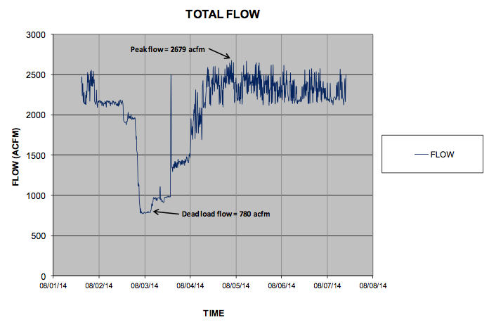
- Typical production flow = 2200 to 2700 acfm
- Weekend flow = 1400 acfm
- Leak load = 800 acfm
- (1) 400hp 2200 acfm and (1) 200hp 960 acfm 2-stage variable displacement fixed-speed screw compressors, good mechanical condition, some controls problems, 10-15 yrs old.
- 400hp compressor turn-down = 1100 acfm (1800 - 900 rpm)
- (2) 150hp 750 acfm screw compressors, fixed-speed, water-cooled, good mechanical condition, some controls problems, 25-30 yrs old.
- Master control system installed but turned off.
- 400hp running in variable displacement, 200hp stuck at 50% displacement, 150hp’s off.
- Common wet header, refrigerated drying, N2 generation, 100 psig
In 2011, the 400hp compressor was converted to water-cooled so that it could run more reliably at full capacity, and the master controls were installed. The control mode that the system was previously set up for was with the master controls was as follows:
- 0-960 acfm (never ran here): 200hp load-unload, 400hp off
- 960-2200 acfm: 400hp compressor, running in variable displacement mode with unloading
- 2200-3700 acfm: 400hp compressor, running in variable displacement mode, (1) 150hp running full load
Average efficiency was good, 5.53 acfm/kW.
In 2014, we recommended repair and improvements, including the following:
- Re-commission master controls (they were shut off for some reason). Efficiency had dropped to 5.35 acfm/kW.
- Retrofit 400hp compressor with a VFD
- Re-program master controls to control VFD compressor
- Reduce demand
- Segment high/low systems, install small high pressure compressor.
The food processing plant decided to do only project #2, and we talked them into doing #1 as a prerequisite. We calculated that this would save about 10% energy, achieving an efficiency of about 5.90 acfm/kW.
Implementation Steps Recommended for a VFD Retrofit Project:
1. Correct all local control issues with compressors: The compressors have to be able to run properly in “local” before they can be run in “remote”. The following issues were diagnosed and corrected in the case study, prior to re-commissioning of master controls:
- The variable displacement controls on the 400hp and 200hp compressor are pneumatically controlled with a mechanical regulator, and not capable of being controlled by a PLC. We bring this up as the main reason we believe that the master control system was turned off. These pilot valves can be manually adjusted to overlap in the master controller pressure range and can malfunction, wreaking havoc on remote controllability. This modulation control will be adjusted above the master control set point. The inlet modulation point will be set even higher than that, but still within the maximum pressure capacity of the compressor and motor.
- The variable displacement controls on the 200hp were set so low that the compressor never developed 100% flow. It ran at 50% flow or off. That will be adjusted up, above the auto control setting.
- The inlet valve on the 200hp compressor would not close. When the compressor tried to unload, the blow-down valve vented the sump, the inlet valve mechanism moved to the closed position, but the inlet valve itself did not close. Thus, the compressor delivered somewhere between 25-40% flow when it was supposed to be fully unloaded. The displacement controls were stuck at 50% and the blow-down valve wide open. This will be repaired.
- We tested one of the 150hp in modulation control, and the pilot valve would force the compressor to run 0%/100% back and forth. It could not even control the modulation valve in a stable manner. All electro-pneumatic components on the two older (150 hp) compressors will be replaced.
- Motor maximum current was an issue, so we trimmed the top end by permanently adjusting the variable displacement controls to trim capacity by about 6% and current by about 4%.
2. Modify and test fixed-speed compressor controls for proper remote control: The following changes are recommended. All of these had been done prior in our case, but needed to be verified prior to going into remote.
- Two-position local/remote switch at each compressor, or controller set for “remote” control.
- Remote start and load, and feedback for standby, running, and alarmed. These can either be with relay dry contacts or with bits on the communications network.
- Verify that remote load and start work prior to going into full auto. We installed simple two-position switches that mimicked the control system for testing. Verify that motor current/power comes up to the full load range when remotely loaded, and drops to the no-load range when remotely unloaded.
3. Select the VFD properly.
- We recommend a line filter to eliminate noise reflected back to the customer’s electrical system.
- Include interface controls and PID board. The minimum interface is start/stop and pressure set point. The minimum feedback is current, speed and alarm.
- Select a constant-torque VFD. Positive displacement compressors are constant torque, actually slightly increasing in torque at lower speeds due to slip. Some VFDs are designed for variable torque applications like fans and centrifugal pumps. A constant torque VFD will handle higher current at low speed.
- Select a VFD that isn’t just the lowest cost and is locally supported.
4. Install the VFD properly.
- Enclosure and ventilation issues. VFDs in dusty environments do not do well. They might need to be located in a clean MCC or enclosed properly (dust-proof with cooling fans).
- Distance from motor to VFD. Special wiring might be needed.
5. Motor issues to consider:
- If the motor is TEFC and/or in a hot area, we recommend improving cooling and installing a motor RTD and alarm.
- Check motor suitability for VFD operation. Some motors do well running on a VFD and some don’t. Consult your motor supplier.
- Install a shaft-grounding brush or ring on the motor to prevent eddy currents being induced in the bearings and premature bearing failure.
6. Control the VFD itself properly.
- Consider compressor starting and stopping the compressor through the VFD directly. It can be either done through the existing starter in-line with the VFD or with the VFD itself. However, fewer components is simpler.
- Give the VFD a remote pressure set point from the master controller. Let it control pressure on its own PID card and transmitter.
- Locate the VFD transmitter at the same location as the master controller transmitter.
- Integrate all useful VFD operational data into the master controller. At minimum, current (for running and overload condition) and speed (for control of other compressors) is needed.
7. Test the VFD compressor prior to being master-controlled.
- Min and max speed operation. Are all temperatures, current/power and pressure in allowable and expected range.
- AC current into drive should be roughly 50% linear with speed. Power factor will drop, so it might be as high as 60%. Current to motor needs to be within motor service factor. Overloads might need to be adjusted.
- Oil temperature differential should not change a lot. The oil flow will drop the same percentage as the heat rate. Excessive differential is not good, indicating low oil flow.
8. Test VFD compressor controls in local control: Make sure the gains and timers are set correctly on the PID board, particularly the proportional control settings. The pressure and speed should be stable within about 2 psi of set point with varying load.
9. Program master controller for “target” algorithm: This is an algorithm that maintains the “base-load” compressors (all but the VFD) in a pressure differential that encompasses the VFD range, using the VFD set point as the “target”. See my article Compressor Sequencer Problems and Solutions for more information on target sequencers.
In summary, we believe that some projects are best engineered using a VFD retrofit. This is not a majority. However, since it is usually neglected, we recommend it be looked at during the planning phase. If the VFD retrofit project is lower cost, better integrated, and more reliable than a new VFD compressor project, it should be considered as a viable option.
For more information, contact Tim Dugan, P.E., President, Compression Engineering Corporation, tel: 503-520-0700 or visit www.comp-eng.com.
To read similar articles on Air Compressor System Assessments, visit www.airbestpractices.com/system-assessments/compressor-controls.


