This aluminum mill spends \$369,000 annually in energy costs to operate their compressed air system. This system assessment recommends actions reducing annual energy costs by \$120,000 and improving productivity and quality by delivering clean, dry compressed air.
Supply-Side System Background
There are three “compressor rooms” providing compressed air to the mill; the Hot Mill Room, the Remelt Room, and the Cold Mill room. This aluminum mill has grown over time but now has no expansion plans in the foreseeable future. The rooms have a mix of centrifugal and three-stage XLE reciprocating compressors Some of the air compressors were installed in 1973 and the most recent significant compressed air system project (with new air compressors) was done in 1987.
Compressed air drying is performed by both desiccant dryers (blower purge and heatless) and by refrigerated dryers. Some of the dryers and piping cause short cycling by the air compressors. Today’s dryers deliver -40 ºF dew point air from some and +40 ºF dew point air from others. The result ends up with a wet system while still spending \$43,000/year in dryer-related electrical energy costs.
The mill operates 8760 hours per year. The mill is located in the “Rust Belt” and the power rate is \$.0325/kWh. Plant personnel, however, inform that significant rate increases are expected in the future.
Today, we have over 12,600 scfm of capacity on-line and while we were monitoring had 10,500 scfm capacity running. The plant was taking 6300 to 6500 scfm due to the “choked flow” out of each compressor room.
Operating under this situation, the system entry pressure fluctuated from below 80 psig to almost 100 psig – average fluctuation 12-13 psig. This is caused by the restrictive piping first causing pressure drop then overdriven pressure during recovery with very short cycles.
The compressors are not loading or unloading in response to system needs but in response to false signals generated in the small, turbulent piping. In all probability, 7000 scfm is probably all the air that can be jammed through this piping and still hold reasonable, if erratic, pressures.
The Over-All Action Plan
We intend to create two compressor supply areas capable of flowing up to 10,000 scfm to the plant in a smooth, efficient manner. One room, the existing Hot Mill, will provide oil-free compressed air with two 3600 scfm class, 3-stage centrifugal compressors and new 4400 scfm heat-of-compression compressed air dryers.
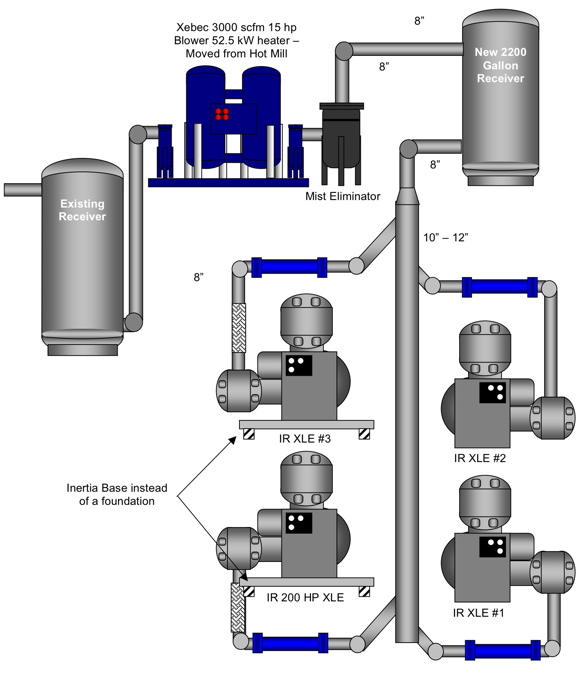
The second room will be the existing Remelt Room, whose complement of three existing 150HP XLE reciprocating, lubricated compressors will be augmented by one more XLE moved from the Hot Mill for a total of four units (total scfm 2930 to 3112 depending on configuration of fourth unit).
The existing Cold Mill room will need some piping reconfiguration if it is to be used at all. We view these units as emergency backup.
With these modifications, today’s demand will be satisfied better with a $94,776 reduction in electrical energy cost. We will also be running fewer units with a commensurate reduction in maintenance and repair costs. Your records can quantify this.
The quality of air will be improved as all the air going to the system will be -40ºF pressure dewpoint class. The system will be dry after the “run in” period.
The electrical energy cost to dry the compressed air will be reduced by \$26,000/year – for a total compressed air system annual electrical energy savings of \$120,000/year.
Reliability – the new configuration will support a 7000 scfm demand with “N + 1” reliability or a “firm 7000 scfm supply”. There is enough backup that if the largest single unit is down for service or repair, additional air supply will not be needed to run.
Specific Actions Required in the Hot Mill Room
The Main Action Item
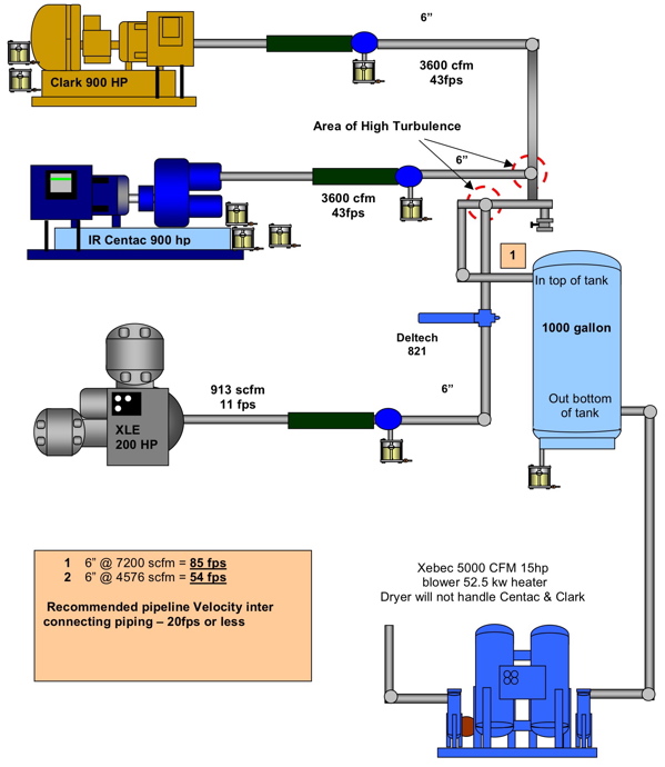
Move the 200HP XLE to the Remelt Mill. Our testing discovered that the piping system in the Hot Mill Room was creating a high back-pressure on the Centac and reducing it’s outlet air flow. The high back-pressure was created by the “high-velocity crossing-tee connection of the Centac and XLE air compressors. This crossing-tee created significant flow resistance and backpressure - which in a centrifugal mass flow compressor shows up as reduced flow (not increased power as in a positive displacement compressor). The plant personnel were amazed to see that the actual measured flow to the dryers in the Hot Mill Room was 800 scfm more when we turned the XLE compressor off and ran the Centac alone!
The numbers below show what we measured during our test:
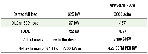
After the shutdown of the XLE, we now have:

Other Action Items
- Move blower purge desiccant dryer to Remelt Mill where it will replace the refrigerated dryer.
- Remove old piping from dryer to receiver to system and replace with 12” stainless steel Schedule 10 piping with pre-mounted valve connections.
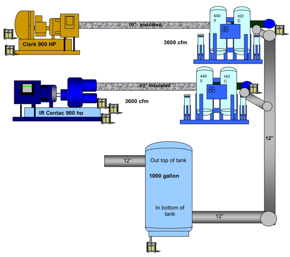
- Install one new, 4400 scfm rated, heat of compression dryer each for the Ingersoll-Rand Centac and Clark centrifugal.
-
- The dryers will have their own aftercooler rated for 4000 scfm. The existing aftercoolers will not be needed. They may be used on the back-up compressors in the Cold Mill Room, where they will be oversized.
- The pipe from the compressor to the dryer should be 104 stainless steel, Schedule 10 and insulated to retain heat and support dryer performance.
BEFORE
Hot Mill Room Before Reconfiguration
AFTER
Hot Mill Room After Reconfiguration
Specific Actions Required in the Remelt Mill Room
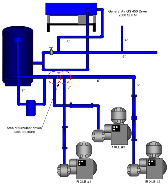
• Reconfigure piping to eliminate current small high turbulent pipe with new main header.
• Rotate and reorient #2 150HP XLE mount on Amber booth inertia base. Cut back top of old foundation, follow instruction.
• Install 200 HP XLE from Hot Mill alongside #2 oriented as shown in schematic. Install on similar Amber booth inertia base.
• Reconnect #1 and #3 150HP XLE’s as shown to header.
• Install blower purge desiccant dryer (from Hot Mill) with current filters as shown in schematic. Eliminate the refrigerated dryer.
• Install new 2200 gallon vertical air receiver (in bottom / out top) as shown in schematic.
• Install mist eliminator pre-filter ahead of existing pre-filter as shown.
• Add dewpoint demand controller.
• Add central control system to keep all units at full load except one at part load – all others off.
• 4” line to shop appears to just feed leaks. Air pressure as we go forward will be too low for effective tool use. We understand the shop has it own air compressor. Check to be sure shop compressor is adequate or acquire one – shut off this 4” line.
BEFORE
Hot Mill Room Before Reconfiguration
AFTER
Hot Mill Room After Reconfiguration
Specific Actions Required in the Cold Mill Room
In order to run these two units together effectively, even in backup, some basic modifications are required.
• Correct the aftercooler problem. Possible to use coolers from the centrifugals in Hot Mill.
• Be sure dryer is ok. If not, may be able to use the refrigerated dryer from the Remelt Mill.
• Increase line size from compressor discharge to header from 3” to a minimum of 4”.
• Connect to header with directional angle entry rather than tee and crossing tee.
• Change header size from compressors to dryer and system from 6” to 8”.
General Piping Considerations (applies to all rooms involved):
- Our sketches are schematics and are not intended to be used as engineering drawings to build to. Follow good piping practice and all applicable codes.
- We have specified stainless steel, schedule 10 main piping for several reasons:
- Black iron pipe requires schedule 40 and is heavier.
- Black iron pipe as gone up in cost and stainless steel is much closer in price.
- All compressed air condensate is very acidic – in an oil free application (Hot Mill), it is very aggressive without the presence of oil which is normally basic to neutralize it. Stainless steel will resist this best. Black iron pipe, unless coated, etc., will rust internally and self-contaminate.
- Stainless steel pipe can be welded or installed with victaulic fittings with viton seals. It generally should not be threaded for compressed air because it will tend to leak.
- Use long Ells not 90º turns. 45º directional angle entry not tee’s. NO “dead head” or counter flow. Observe pipe sizes called for.
- Install zero loss, automatic condensate drains on all risers before dryer. Also install on aftercooler separators, receivers, etc.
Summary
After the piping and equipment have been reconfigured in the Hot Mill and Remelt Mill, the aluminum mill will now have:
- Air available to the system in a smooth flow pattern with an average 2-3 psig pressure loss compared to the current 11-15 loss today. This will stabilize production line pressure significantly.
- Dry air instead of wet air.
- Annual electrical energy cost reduction of about \$120,000/year.
- Fewer compressors on-line to produce the air, lowering the overall maintenance and repair costs.
- Firm air capacity of 7000 scfm with redundant backup air even with the systems largest single compressor down for maintenance or repair. This will enhance reliability but also allow proper scheduled maintenance of the equipment.
For more information, please contact Hank Van Ormer, Air Power USA, Tel: 740-862-4112, email: [email protected], www.airpowerusainc.com.


