Introduction
What if you just acquired a delivery business that used to deliver large equipment, and now you are re-tooling it to deliver a random mix of small and large packages? You inherited two fairly modern 18-wheelers (4000 cubic foot capacity) and two ancient 26-foot (1500 cf) furniture trucks. The old boys don’t always start, and need a lot of TLC to keep running. The new ones run beautifully, but are way over-sized for most loads over 4000 cf. Without consulting you, your new purchasing manager just spent a fortune on two new little 22-ft (500cf) hybrid delivery vans. Now, your dispatcher has to match loads to trucks, and it is driving him crazy to figure it out. Before the hybrids were purchased, your dispatcher ran the big two new ones, with one full and the other taking the rest, mostly empty most of the time, and kept the old boys for standby in an emergency. Your fuel bill was astronomical, but it was simple. The big trucks get four mpg full and six mpg empty. Now you have these tiny new trucks, and you’re scratching your head, “How do I manage the whole fleet at lowest cost, and still meet demand?” The new trucks are great, but too small! What if my demand changes daily, and varies from 3,000 cf to 9,000 cf?
How Can One Get Centrifugal and Rotary Screw Compressors to Work Together?
This is exactly the situation I had in a recent compressed air project. I helped the customer solve the problem and they saved over \$400,000 per year in electricity through “Flow-based Controls.”
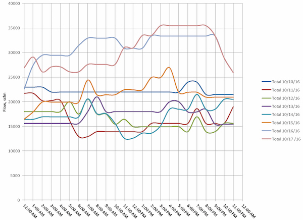
A large pharmaceutical company needed huge flow rates of 30 psig air to aerate multiple fermentation processes which create food-grade materials. Flow could vary from about 12,000 scfm to 35,000 scfm. There were a variety of batch processes, mostly running independently. An hour-by-hour schedule for anticipated air flow is developed every afternoon for the next day. Based on that schedule, the boiler operators run the air compressors that can handle the load range for the whole day. See Figure 1 for one week of actual projected data. In reality, the peak flow can be higher than anticipated. These flows are calculated from the sum of the hourly projected flows, and the anticipated peaks are not always happening at the same time. If the peaks are concurrent, the total can be higher. Conversely, the total minimum might be less.
Figure 1. Typical One-Week Compressed Air Flow Profiles
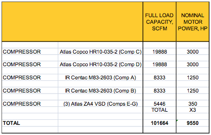
The air compressors available to the site, including the new ones are shown in Table 1. Just prior to my getting involved, they had bought three small (350hp) single-stage VFD compressors. Together, they are slightly larger than half the size of one old Centac, and less than 30% of the size of a 3000hp Atlas Copco centrifugal. Prior to the VFD compressor installation, all the compressors were in local control, manually run to match anticipated demand for each 24-hour period. The large 3,000 hp units have good proportional control, and can run from full to min flow with very little pressure variation. The 1,250 hp units, however, aren’t trusted by the boiler operators. Although their curves indicate that they should be able to provide at least 35 psig, when they are run at the same time as the large units, operators believe that they aren’t developing capacity. They weren’t sure if they surge or just blow off, but there is a problem that creates uncertainty to them.
Prior to installing the VFDs, they had to run two 3,000 hp units almost all the time. The anticipated peak was always at least 20,000 scfm, and they didn’t think they could run a Centac and Atlas centrifugal at the same time. The Centacs had local control adjustment problems that didn’t allow them to load up. After the installation of the VFDs, it wasn’t clear to the operators what to do. Anticipated peak is higher than 25,500 scfm about half the time. Savings of about 1000 hp average are possible if this question can be answered satisfactorily, over \$400,000/yr in electricity!
Table 1. Air Compressor Inventory
If you were the boiler operator in charge of starting the air compressors now, with the new VFDs installed, how would you run the compressors? You get one shot to decide, and need to leave them in that mode all day. Your decision needs to be based on the peak anticipated flow and size of compressor that you can reliably run, and with the set of compressors that can run together in a stable manner.
Since anticipated peak flow is rarely between 20,000 and 25,000 scfm peak, the sweet spot for running the VFDs, you would run the two Atlas centrifugals most of the time, and your new VFDs would sit idle. And your savings would be almost zero. That’s the only alternative without master control.
If your engineers or suppliers think you should buy a “sequencer”, don’t believe them. See my 2011 Compressed Air Best Practices® Magazine article for compressor master controls terminology and function, www.airbestpractices.com/system-assessments/compressor-controls/compressor-sequencer-problems-and-solutions.
Sequencers typically are designed for rotary screw air compressors of a similar size, and usually run the last-on compressor as “trim”, either load-unload or VFD. You can’t save any energy by doing that with the two big centrifugal air compressors, because they are already doing the best job they can at that. And the second unit is blowing off 1000 hp of air. You can’t run the Centacs in and out, load-unload like a sequencer does, because pressure variances will be too high. You can’t put the VFDs only in trim, because they aren’t big enough to swing the demand variances that are anticipated in a given day, and the range won’t match to the narrow window that is their sweet spot (20,000 to 25,500 scfm) most of the time.
Deploying Compressed Air Flow-Based Master Controls
What if you could repair the Centacs so that they can operate properly, and master control all seven air compressors so that the optimal set would run in any flow range? Sometimes run one set in one way, and sometimes run another set in another way, depending on total compressed air flow? That is called “flow-based control.”
For instance, in the delivery truck analogy, what if you could automatically deploy the 18-wheeler and trim with the hybrids sometimes, or run an old truck fully-loaded and trim with an 18-wheeler at the top end? There are lots of combinations to think through. And you would need a logistics system that could quickly figure out which trucks to use in real time.
In our project, we were not allowed to automatically start and stop the 3,000 hp Atlas centrifugals due to customer and vendor perceptions of risk to the process and compressors. In reality, they could have been auto-controlled. We were able to repair and adjust the Centacs so that they were able to fully load at required pressure, and remotely start and load. We were not able to control their pressure remotely, however. That would have required new inlet guide vane (IGV) and blow-off valve (BOV) controllers, new transmitters, and local PLCs, which was more than our customer wanted to spend on these older compressors.
We had the customer install a smart master control system from TTED called a PL4000, programmed to control different sets of base and trim compressors in each possible flow range, from zero flow to maximum. See Figure 2. The system was commissioned with zero blow-off. Projected performance assumed some blow-off, so this exceeded expectations! Table 2 shows how we did it.
Figure 2. Flow-Based Control System
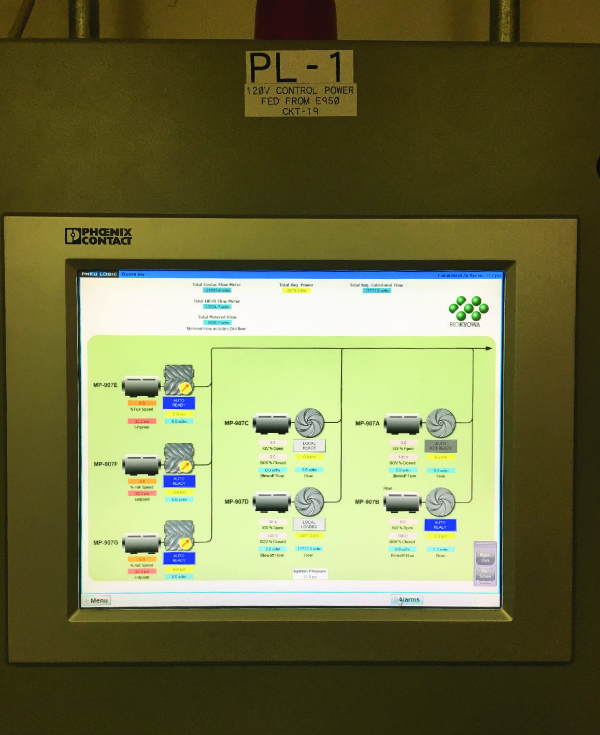
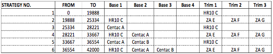
Table 2. Flow-Based Control Strategies
How Was This Done?
In simplified form, we merely had to have auto control of the Centacs and VFD compressors, a reliable flow metric, a table of flow ranges and compressors, and a solid algorithm to shift from one table to the other. Shifting the compressors has to happen without pressure varying more than the programmed operating range. If pressure drops to a floor (a differential below target pressure), the active strategy shifts up one. If flow drops below the lower threshold, the strategy shifts down one.
1. Installed Control and Monitoring Interfaces for Five Compressors
Ideally, we wanted to be able to control the set point, start/stop, and load-unload of all compressors. The problems were:
- The Centacs didn’t have electronically-controlled IGV and BOV, so their set points couldn’t be controlled remotely.
- The HR10’s were only monitored remotely, not controlled.
So we only could control five automatically, the two Centacs and the three VFDs. And we had to depend on operators to select the right number of HR10’s to run each day. Typically that was one.
Next, we had to adjust the Centac local IGV’s and BOV’s and wire interfaces for load and start to the old Centacs. This required some maintenance, testing called “surge testing” and minor electrical modifications. We got the Centacs adjusted to fully load to about 35 psig (master set point was about 31 psig) without surging, and then wired start and load relays to the controls.
For the new VFD compressors, we had to get the Modbus gateway working that allowed the PL4000 to talk to the compressors, and give them a set point for VFD control, a start point below that, and a stop point above that.
2. Developed a Reliable Flow Metric
At first, we planned on using two flow meters, one for the HR10’s and one for the Centacs, and calculate capacity of the VFDs based on motor speed. Then add them up. The flow meters were troublesome and unreliable, being thermal mass type in wet compressed air. And the vortex-shedding types were not pressure and temperature compensated, so we had to go to Plan B, calculated flow, as follows:
- VFD compressors: Got motor speed feedback for each compressor, and calculated capacity as % speed x full load acfm, if loaded.
- Centacs: Got motor current (via a current transmitter) and BOV valve operator pressure (via a pressure transmitter), and calculated capacity from estimated full load capacity and valve % open.
- HR10 Centrifugals: We got IGV, BOV, motor current, and pressure feedback from the PLC, via the network connection.
- We summed all compressors’ flow to get total flow, and smoothed it mathematically to “de-bounce” the signal.
This metric turns out to be more reliable than from flow meters, because the measurement sensors are simpler and less likely to fail, and the calculations are not dependent on ambient conditions.
3. Implemented a Solid Algorithm
Table 1 is the commissioned algorithm. We didn’t have to try many alternatives. The main issue in testing that was needed was the pressure settings. Without getting into two much technical detail, the trim compressor set points had to be adjusted multiple times to get to work in all flow ranges. Sometimes the VFD compressors controlled pressure as “trim” and the centrifugals were all base-loaded. Other times, the HR10 compressor controlled pressure as “trim” and the VFDs were off. The pressure ranges couldn’t overlap.
4. Tested All Strategy Shifts
This is the most important part of testing, and the one that presents the most risk to the process if not done right. Thus, off-line testing was essential. Another article is going to describe this. In a nutshell, the strategy up-shift point (lower pressure trigger) needs to be adjusted to not be too low to create a process problem, and the strategy down-shift flow points need to be adjusted to not allow a pressure spike, nor to create a “dead-band” problem where the shift-up has to immediately happen. We reproduced every strategy shift, by off-line testing, then tuned the system. Then, we watched the shifts occur in the live system, and did a small amount of additional tuning. This took several days, and multiple issues were discovered and corrected before going “live”. Live testing was thus very smooth and uneventful.
Conclusion
This project really got started-up - and it really runs. This is not a “study” with “potential savings if …” We actually got the system to run with one 3,000 hp compressor OFF all the time, and the customer is trusting the automation system to run the best combination of the other “small” air compressors. The baseline and improved system performance is shown in Tables 3 and 4. The savings are over 5,500,000 kWh/year! That’s a huge compressed air savings project. And total cost for the controls is less than the cost of one of the little VFD air compressors, which now can actually run in the mix properly.
Table 3. Baseline System Performance
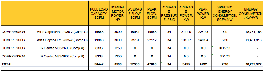
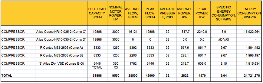
Table 4. Optimized System Performance
For more information, contact Tim Dugan, tel: (503) 520-0700, email: [email protected].
To read more Air Compressor Controls Technology articles, please visit www.airbestpractices.com/technology/compressor-controls.


