Audit of the Month |
|||||||||||||||||||
|
|||||||||||||||||||
|
Assessment Objectives
The facility is a plastics injection blowmolder and is a division of a large corporation. The following information was produced from a compressed air system assessment done over seven days.
The compressed air system at this facility has been somewhat unreliable with quality problems that have escalated in the last several years. The compressed air system has significant water carryover to the process causing excess maintenance on machinery components. Lack of system reliability means the standby compressor(s) cannot be brought on line in a timely manner to prevent a process interruption. Typically, this type of shutdown happens only once or twice per year, but it triggers an expensive restart of the production machinery. As for operating cost, it is likely the system can be operated on a compressor half the size of the existing machines, even after the new production machinery is installed.
This compressed air assessment was proposed in order to determine the future needs of the plant with the proposed additional blowmolding equipment being installed, to remedy the quality issues, and to identify a project to accomplish these goals. The focus of the assessment was to examine:
The root cause of water carryover to the system and provide resolution.
The heat stakes on the D471 machines to determine the actual consumption of compressed air per unit and assess the impact on the compressed air system of adding similar machines to the production process.
Determine the best fit compressor combination for existing and future needs.
 |
|||||||||||||||||||||||||||||||||
|
|
||||||||||||||||||||||||||||||||
The Air Compressors
The plant currently operates one of two 250 HP LeRoi two-stage rotary screw air compressors to generate the approximate 580 SCFM consumed during normal production in the plant. Given the site conditions at the time of this work the compressor(s) were each capable of generating 1200 Scfm at full load on average. There is also a 100 HP Kaeser compressor being installed to act as a trim compressor for either of the existing LeRoi compressors based on anticipated needs from adding process machinery. The current energy costs for the system are \$123K per year at the energy rate of \$0.075 /kWh.
The existing compressor operates fairly efficiently but because it is more than 2.5 times larger than what is needed and operates at a relatively high sump pressure in the unloaded state, it never reaches less than 50% of full load power in the unloaded condition before it reloads to restore system pressure to the unload set point. Utilizing the Kaeser 100 HP compressor being installed will meet the existing demand more efficiently; the new D471 machinery will likely require that a second 100 HP be installed so the LeRoi 250 HP compressor can remain in standby while overall system efficiency is retained at its maximum Scfm/kW.
Compressed Air Quality
The dryers in the compressor room simply do not work. It was thought at first that bed contamination from oil carryover was the key suspect; over the long term this may be true but not as the root cause of the current problem. Dryer #2 operates with the #2 LeRoi compressor in a train, or, dedicated installation as do LeRoi #1 and dryer #1. From a reliability standpoint this means if one dryer is down for repair the other compressor and dryer must be used, meaning they must both be in good repair and ready to operate.
Because neither dryer is functioning properly and the purge of the #2 dryer alone represents 44% of the plant demand for air (plus the cost of operating its heater), it makes good economic sense to scrap these dryers in favor of the Kaeser refrigerated dryers located in the compressor area, installing a third dryer that matches these two will provide redundancy but is not required in the short term to fix the moisture carryover problem and certainly provides no cost savings opportunity. Because the demand in the plant is not expected to exceed the capacity of one dryer, even after adding new production machinery, the two dryers represent 100% redundancy.
The two dryers must be placed in a parallel piping arrangement to assure they are capable of servicing the needs of any combination of compressors that might be used.
Stability of Compressed Air Pressure
This is another facet of compressed air quality that is rarely addressed in system design. Currently the system pressure to production swings more than 8 psig. Production management indicated that this was an issue when setting up process machinery for repeatable results. The reason this happens is inherent in the nature of load/unload controls and will not change with the installation of the Kaeser compressor (same type of control). Installation of a pressure/flow control will stabilize the system pressure to production.
The ideal situation is to allow the compressors (supply side) to operate at/near their design range, making load/unload, start/stop, etc. decisions while the demand side is held at a steady pressure somewhat below that level but high enough to support all demand side requirements on a repeatable basis. This is done with system pressure/flow controls and requires adequate storage upstream in receiver capacity. The existing 2200 gallon tank is large enough because of its capacity versus the largest system event (loss of a compressor) and the control range available between the lowest Supply Side operating pressure and the highest Demand Side requirement.
At present it is reported that the true pressure requirement on the process floor is 65 psig, the point where machinery will alarm and shut down. The pressure flow controller would be set somewhat above that as the target goal, say 75 psig, and this would then be the plant pressure specification going forward. All new equipment whether it is a small pneumatic tool or a large assembly machine must be able to operate at this pressure or have their own local supply of compressed air installed and maintained by the owner of the tool or equipment.
It is idealistic to assume the pressure/flow control would be set at 75 psig immediately after installation. The best approach is to set the controller at or near the existing pressure range minimum since the plant currently operates satisfactorily at this level. The pressure can then be slowly lowered to the target of 75 psig over time; during that time there may be point of use issues not revealed during this study that will need correction to accommodate the lower system pressure.
Reliability
Reliability means that the compressed air system will support the largest event in the system without production suffering any ill effect. These events can be a large end user on the Demand Side or the loss of the largest compressor on the Supply Side. At this plant it is the latter that will impact the process since there are no demand side users larger than the loss of any of the installed compressors.
In the previous section, air quality and reliability are within reach but the current operating philosophy must be changed to ensure reliability. Presently the loss of a compressor means that pressure falls to the local alarm set points on production machinery (approximately 65 psig). Then maintenance personnel scramble to find out what is going on, resulting in the startup of the standby LeRoi compressor. This almost always results in an expensive restart of production. Many hours of production can be lost although the costs are not included as part of the financial opportunities presented in this report.
Reliability and quality both depend on stabilizing pressure to production, having adequate storage, and a good control strategy. It is recommended that as a minimum, the three compressors be automated such that the ideal combination can be operated and that standby compressors can start without negative impact on production. Since it is recommended that one of the LeRoi compressors be removed and a 100 HP of similar size be installed to act as trim to the existing Kaeser compressor, only the existing Kaeser compressor will need to be retrofit with automatic start controls. Maintenance people reported that the LeRoi compressors have these controls, and the new 100 HP compressor can be priced with this option during the bid process.
|
||
| "Annual energy savings of \$62,000 will be realized." - Gary Shafer, iZ Systems |
It is not necessary to install central automation unless the plant personnel opt for this. Until the new production machinery is up to full capacity, it is anticipated that the Kaeser compressor will handle the demand on its own once the desiccant dryers are removed. After the new machinery is installed, there will only be occasions where the second machine might be needed but this is unknown. It is estimated that the plant demand will approximate 400 scfm after the new machinery is installed; a number so close to the rated capacity of the existing Kaeser compressor it is impossible to predict how often a second compressor will be needed to trim for the first.
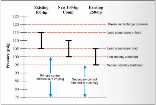
In order to start the standby compressor in time to back up the loss of an existing compressor there must be adequate storage in the system. To calculate the storage requirement the control pressure profile must be constructed as follows:
 |
||
The above control strategy represents a simple cascade arrangement that might be used in this system. Another option might be to use an embedded array where the lead compressor pressure band is “inside” the secondary which is “inside” the standby. That type of arrangement is much more difficult to set up especially if the lead and lag compressors are changing in a weekly rotation on a manual adjustment. For now it is assumed that the LeRoi compressor will remain in the third (standby) position and the two 100 HP compressors will be alternated in and out of the lead positions on a normal basis. This means the maximum control differential is approximately 20 psig and that is what the storage capacity must be sized for. Assuming the LeRoi compressor can start and load within a 20 second interval, and the largest event is the full capacity loss of one of the 100 HP compressors (450 Scfm), storage capacity is calculated as follows:
Total storage on the Supply Side, upstream of the pressure/flow controller needs to be a minimum of 785 gallons. The existing volume in the receiver alone is 2,200 gallons, nearly 3 times what is needed for this control strategy including all piping and miscellaneous volume, such as that contained in filters and dryers as an example.
Operating Costs
Installing the Kaeser compressor and both refrigerated dryers (and scrapping the two desiccant dryers) will solve two problems in the present; the single compressor will handle today’s plant demand and the associated dryer will drop the pressure dew point and help eliminate moisture carryover to the plant. Note that lowering the dew point can only “help”; moisture carryover can be caused by other things such as poorly operating drain traps. The existing traps are all in various states of repair and only two have malfunction alarm lights (one is currently flashing at the receiver), otherwise there is no way to tell if any of the existing traps are working. Along with installing these dryers and filters, assure that the traps are working; new positive visual feedback traps that do not waste air are recommended for the future.
Further, the primary benefit of installing the refrigerated dryers and scrapping the two desiccant dryers eliminates the manufacturer’s stated 135 Scfm of purge air and the average 6.4 kilowatts of heater power. This purge air rating is directly related to the purge orifice regulated pressure setting; the manufacturer’s specification is based on a 45 psig setting, the actual observed was at 90 psig. This means the purge air could be as high as 240 Scfm but from closer analysis of the amperage draw on the LeRoi compressor it is found to equate to roughly 180 Scfm and 34 kW, these are the numbers being used in the calculations in this report.
Conclusion
With plant demand averaging 580 Scfm during normal production and 400 Scfm during low production periods, it is apparent that the LeRoi compressors are too big for this facility to operate economically. Not only will they consume more energy but they will cost the same to maintain as they would in a facility using 2_ times as much compressed air. Currently the electrical cost to operate the LeRoi compressor and heated desiccant dryer approximates \$123,000. Operating the Kaeser compressor and dryer at the same demand level will cost approximately \$61,000 annually, a savings ranging near \$62,000 annually. This assumes the desiccant dryers are eliminated.
For the future, the new process machinery will add in the range of 75-100 Scfm total; removal of the desiccant dryers will eliminate 180 Scfm and it is likely that the single 100 HP Kaeser compressor will be adequate to supply the plant most of the year, especially if the compressor room is well ventilated to remove the air-cooled compressor’s heat load. During the warmer months the single Kaeser compressor might not be adequate and one of the LeRoi compressors may once again need to be in operation as the lead compressor.
For more information, visit iZ Systems.
To read more articles about the Plastics Industry, please visit www.airbestpractices.com/industries/plastics.


