A Canadian plastics product plant has upgraded their system of older modulating air compressors to a newer system using a variable speed compressor and a compressor-sequencing controller. This article discusses their challenging experience.
Molded and Blow Molded Plastics Application
The plant produces both molded and blow molded plastic parts on a 5 day per week, three shift schedule. Production and maintenance sometimes occurs on weekends, occasionally requiring the air compressors to run on a 24 x 7 basis so the practice was to leave the compressed air system always pressurized. The system consisted of three modulating lubricated screw compressors one sized at 150 hp and the others 125 hp (3 units), each controlled with their local compressor controllers. The system also had non-cycling refrigerated air dryers dedicated to each compressor. The flow profile had a fairly constant base component, but with occasional high variability depending on what production machinery was running.
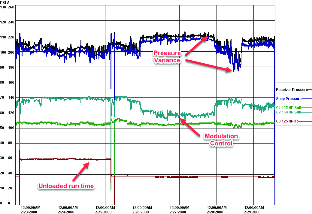
Figure 1: Original pressure/amp profile. Click here to enlarge.
Initial Assessment of Compressed Air System
The local power utility was called in to do a scoping study of the system. Data loggers were placed on the 100 psi system, showing the compressed air system was running inefficiently due to modulating compressor control. In modulating control, the inlet valve of the compressors chokes off the compressor inlet air, reducing the compressor output in response to the system pressure change. As can be seen in Figure 1 when this modulation happens there is a reduction in compressor amps as the pressure rises. The other smaller 125 hp compressor amps rises at times of increasing pressure, and falls at times when the pressure reduces. This is not modulation but shows the compressor is in drawdown, at maximum capacity, inlet valve wide open.
Around the center of the chart, corresponding to a weekend, the amps of the 125 hp start to go down as the pressure rises. This is a sign the inlet valve is closing under light loading, creating a worst-case scenario, two modulating compressors sharing the load. Figure 2 shows a photograph of the inlet valve of this type of compressor in fully closed position.
In addition, you can see a third compressor with much lower amps. This compressor is running unloaded through the first third of the profile and was manually turned off part way in. You can see the unit continues to draw amps even though the motor is not running. This is due to installed power factor correction capacitors consuming amps (not power) when they are energized.
A profile like this presented a problem in estimating the flow based on amps (no flow meter was installed at the time) because a reduction in amps can mean two different things, either full load in draw down or a compressor in modulation at part load. Care had to be taken in simulating a flow profile in this case so estimated savings could be calculated accurately.
The system auditor found the energy consumption was 2,740,000 kWh per year, costing an equivalent to \$267,000 annually at 10 cents per kWh while producing about 1,390 cfm. This energy consumption represented about 10% of the total facility electrical load. The system specific power calculated to about 22.5 kW per 100 cfm, equating to a fair amount for a compressed air system of this size.
The utility calculated a possible 35% savings could be gained by applying various energy conservation measures to the plant and a substantial energy rebate could be granted to pay for the changes.
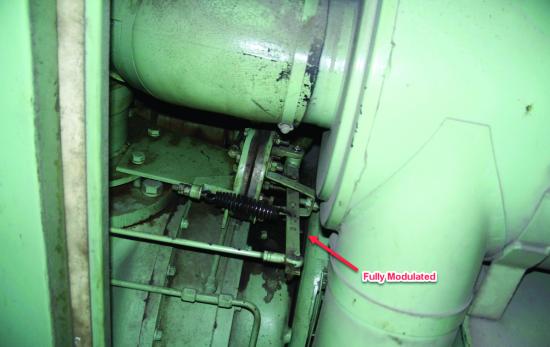
Figure 2: Compressor inlet Fully modulated at poor efficiency.
Integration of VSD and Air Compressor Sequencer
The first recommendation by the utility was to get the compressors under control. Modulation is one of the worst ways to operate compressors at part load. The improvements consisted of three conservation measures. The first was to upgrade one of the older compressors to a more efficient two-stage variable speed unit. This had the potential to renew the compressed air production system, provide better efficiency, and provide excellent part load turn down to match the variable loads. A compressor sequencer was recommended to provide good control of the remaining base compressors, comprised up of the remaining 150 hp and 125 hp. A large storage receiver was added, sized to 2,000 gallons, to make it easier to control the compressors.
The controller selected has an energy efficiency mode capable of selecting the appropriate size compressor to operate based on the system loading. This occurs all the while maintaining the VSD compressor as the trim unit, taking the partial load. The controller senses the pressure downstream of the air dryer and controls the typical sag caused by the dryer and filter pressure differential. The controller is interfaced to the base compressors in such a way as to force the units to full load when they run. Conversely, if the compressor is not required, the unit will unload and turn off using its local automatic start controls. Verification loading showed this control strategy worked very well, with the base compressors only having 1% unloaded run time through the full final profile.
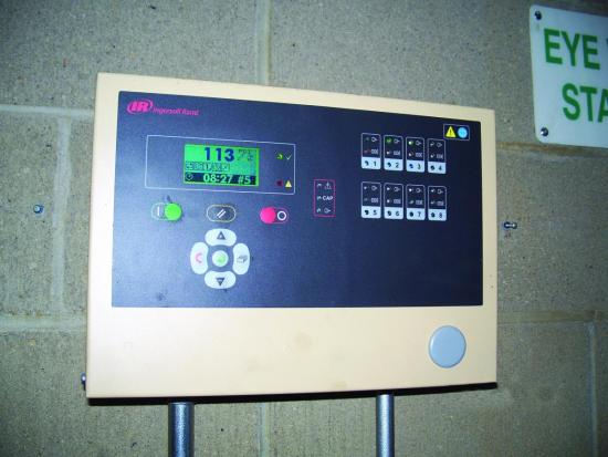
Figure 3: This controller keeps pressure constant while choosing the most efficient compressor.
Combating Artificial Demand from Compressed Air Dryers and Filters
The power utility recommended other changes to the system. The air dryers were non-cycling units consuming a total of about 8 kW at all times. This is almost full rated power, even when the associated air compressor turned off. Purchase of a single new thermal mass dryer sized for all the compressors was recommended to reduce power in proportion to the moisture load of the compressed air production. Figure 4 shows its control tracking energy savings. The overall savings were 78% compared to a similar sized non-cycling unit.
Filter pressure loss, typically 3 to 5 psi, was addressed by installing a mist eliminator style main filter with average pressure drop of about 0.5 psi. Airless drains were installed on the filters, dryers, and compressors to reduce compressed air loss (Figure 5).
The production load was found to be pressure sensitive. Therefore, the higher the plant pressure the more air the machines demanded (called artificial demand). The utility recommended the installation of a flow controller (Figure 6) to regulate plant pressure to a lower level while keeping the compressor pressure a bit higher. This allowed for good control of the compressors without disturbing the plant level.
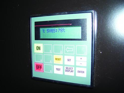
Figure 4: Cycling dryer shows savings to date.
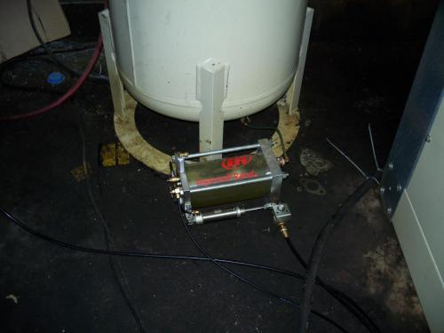
Figure 5: Airless drains save wasted air.
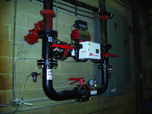
Figure 6: Flow controller reduces artificial demand.
Energy Audit Savings Results
After installation the power utility returned and performed verification logging. This showed the system consuming about 1,242,200 kWh while producing about 1,050 cfm of compressed air. This calculates to a savings in energy of 55%. This was considerably different than the predicted values. The big change was the plant started turning their system off on weekends to save energy. The specific power of the system, when running, was now 18.5-kW/100 cfm meaning a savings of about 18% on compressed air production efficiency. The remainder of the savings was due to reduced compressed air flow and lower operating hours. The utility incentive was over \$100,000 in this case and helped reduce the simple payback of the new equipment to an agreeable level of under 3 years.
Proper Installation & Sizing of VSD Air Compressors – Webinar RecordingDownload the slides and watch the recording of the FREE webcast to learn:
|
Subsequent Compressed Air Data Logging Finds Problem
A number of years later the power utility approved another data logging by the compressed air supplier to check if the savings in the original verification were sustained. The assessment found most of the compressed air production equipment was operating adequately, but unfortunately, the compressor controller had malfunctioned, unknown to the plant operators. This caused one of the compressors to continue to run over the weekend in load/unload mode, even though there was an efficient two-stage compressor available. The plant had no way of monitoring the efficiency of the compressed air system, so energy efficiency had inadvertently slipped. The plant realized this after discussion with the utility and corrected the situation.
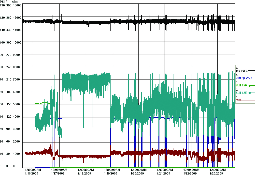
Figure 7: Final profile (plant pressure not shown). Click here to enlarge.
Conclusion
This project shows the kind of savings that can be gained by not only replacing compressors, but also correcting the control through use of an intelligent sequencer and added storage capacity. Additional measures like efficient air dryers and flow control made for extra savings on top of what the efficient production equipment could deliver. Of course, a substantial savings was gained by simply turning off the compressors during non-production hours. Despite good control being in place, the extra logging showed if the system efficiency is not monitored, the operation of the system could become less efficient as time goes on.
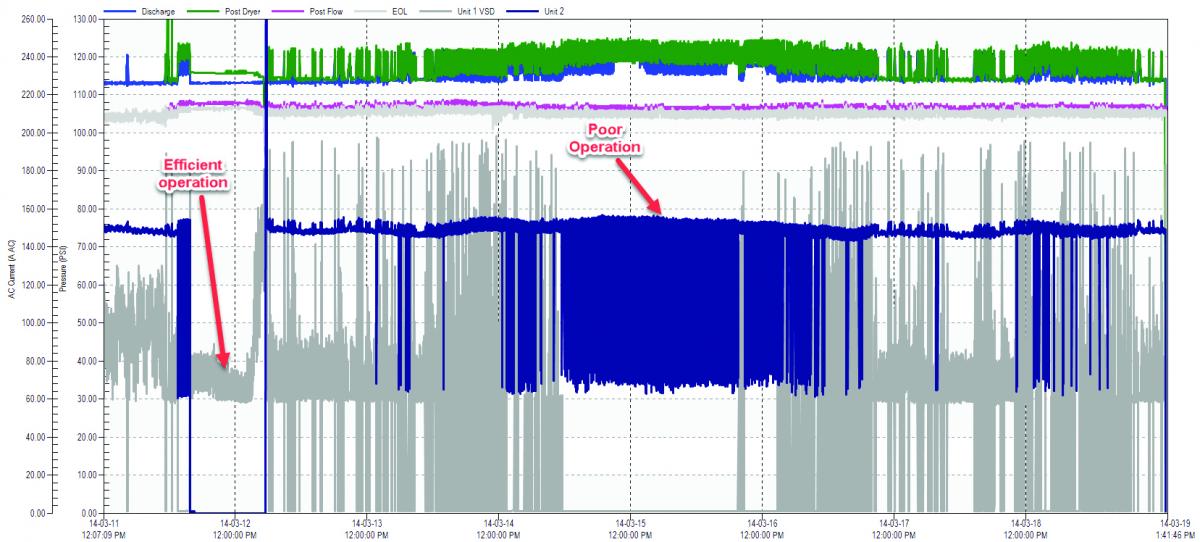
Figure 8: Second logging years later showed problems. Click here to enlarge.
For more information contact Ron Marshall, Marshall Compressed Air Consulting, tel: 204-806-2085, email: [email protected].
To read more Plastics Industry articles please visit, www.airbestpractices.com/industries/plastics.


