Audit of the Month |
||||||||||||||||||||||
|
||||||||||||||||||||||
|
||||||||||||||||||||||
|
Best Practice Guidelines for Boiler Soot Blowing
Utilities have been cleaning their boilers for many years using either steam or high-pressure air. In the past, when air was used, due to the size of the boilers and the reasonable quality of fuel used, a relatively small amount of cleaning was required.
In the past decades, larger power-generating stations were built and the quality of fuel was deteriorating, requiring a greater amount of cleaning with shorter cleaning cycles.
With these changes, larger compressors, when air cleaning, became a necessity. Reciprocating compressors were unable to compete on an economic basis in the larger capacities due to their relatively small capacities, initial cost, high installation costs, and space requirements for multiple compressor installations. Centrifugal compressors have been used in utility soot blowing in a limited amount since the early 1950s, but the reliability and efficiency of early high pressure designs left a great deal to be desired.
From the late 1960’s through the early 1980’s, compressor manufacturers took great strides in the development of the high-pressure, multi-stage, centrifugal air compressors, utilizing the advances in centrifugal technology and manufacturing capabilities. They extended these advances in efficiency, reliability, and compactness to the high-pressure units (300 to 500 psig). This makes them the most viable option for economic large volume, high-pressure compressed air, such as required in a soot blowing system.
Air vs. Steam for Soot Blowing in Boilers
Generally speaking, soot blower manufacturer’s lances, with some modifications, will handle either cleaning media steam or compressed air.
Cleaning energy is usually defined as:
Fluid Horsepower = WV (Px 144)/33,000
where: W is Flow in lbs/min
V is Specific Volume in Ft3/lb
P is Psig at the nozzle
This fluid horsepower relates equated kinetic energy at the point of impact to relate to the surface soot removal. This relationship is called “peak impact pressure.”
A nozzle designed properly for air or another designed for steam will clean an area equally effectively. Other more important criteria that are used to determine the boiler cleaning media are listed below:
- Geographic Location – An area that has quality water available may be more prone to use steam.
- Quality of Water – chemically hard water would be a detriment with a steam cleaning system due to the high cost of chemically treating the water.
- Capacity of Steam or Air - An excess of steam or air due to operational changes may influence the decision including operator familiarity and comfort with either media.
Looking at air vs. steam on an economic basis:
Steam Vs. Air Economics |
Air |
Steam |
| Operating Cost | Aproximately equal but depends on quality of steam used and quality of Hâ0 make-up | |
| Initial Cost | Purchase of a compressor is a large negative | Steam capacity can be built in at a moderate cost or may be already available |
| Piping Cost | Air piping is generally less expensive than steam | Steam system is very expensive with piping insulation, steam traps, drip legs, etc. |
| Reliability | Obtaining adequate reliability for constant sustained use requires a redundant compressor | Steam available as long as boiler is in operation |
| Manteinance of Piping and Systems | Air piping is usually low maintenance | Steam piping sistem requires higher maintenance |
| Equipment Maintenance | New compressors add to the maintenance-required effort | The boiler is already being maintained |
| Off-Load Capability When not Needed | Larger horsepower centrifugal compressors do not readily shut downfor short duration and often must stay on running inefficiently | Steam can easily be turned off and on |
Deploy a Dedicated Low Pressure Air Compressor
Often because the large horsepower high pressure compressors cannot easily be shut off and also have to run the low pressure (100 psig) plant, service and instrument air is taken from the high pressure receiver that is regulated down to the low pressure. This is very inefficient compared to running a dedicated low pressure compressor.
On a recent compressed air audit at a Midwestern power plant we developed the following data profile. All costs are based on the power plants selling price of electricity \$0.06 / kWh 8760 hours per year. The progressive thinking here is “If you don’t use the energy to produce electric power – you can sell it”.
All the compressed air high pressure and low pressure was supplied by the High Pressure “Soot Blowing Compressors”, 12,500 scfm at an annual electrical energy cost of \$195.99 scfm / year or \$2,449,876 per year.
The low pressure system has been supplied since the mid 1990’s by the high pressure centrifugals and regulated down to the 100 psig class level. Initially the low pressure air demand was relatively small and it made more sense to use regulated low pressure rather than start up another low pressure compressor and still not being able to shut off any of the three 2000 HP high pressure centrifugals. In effect the low pressure air compressor would be on and the large horsepower centrifugal would go into “blow off” with no net input energy savings, and probably a net increase into the compressed air supply. During the last decade the low pressure demand increased and the utility called for us to evaluate the total system. Measurement and observation gave us the following demand profiles:
| Estimated low pressure demand: | |
| Ash air | 1469 scfm |
| Control air | 1212 scfm |
| Station air | 2334 scfm |
| Total | 5020 scfm |
| Estimated high pressure demand: | 7480 scfm |
| Total air flow | 12,500 scfm |
At the end of the audit and implementation, air conservation programs reduced this to:
| Low Pressure air | 4020 scfm |
| High Pressure air |
6730 scfm |
This low pressure demand was satisfied with 6000 scfm base load compressor and 1400 scfm of VSD driven trim unit. The remaining 6730 of high pressure air (300 psig) demand was satisfied by running one of the 2000 HP original units and a new additional 1500 HP smaller centrifugal with 25% turndown. The newer unit is then 20% more power efficient then the original with almost 15% more effective turndown.
- The new 1500 HP compressor was more power efficient than the older 1995 units due to better manufacturing and advanced design.
- The smaller centrifugal with more effective turndown was applied to the demand at 75% flow, 80% power and generally “not running in blow off”. Previously the three older units were all running normally with two in “Blow Off” this improved the overall high pressure efficiency about 20%
- The low pressure was obviously producing at a much better specific power. An improvement of 48% compared to the previous high pressure air regulated down.
- The total savings reduced the annual electrical energy cost by 43% or \$1,387,638 per year. The total project cost was \$1,462,700, a simple payback of a little over one year (12.6 to 12.2 months)
Other Soot Blowing Operational Considerations:
Tube Erosion
When steam is used as a cleaning medium and a soot blower starts is blowing cycle, there normally is a temperature differential between the soot blower and the steam. When this happens, steam condenses and slugs of water are ejected from the soot blower nozzle. After repeated cycles, the slugs may erode the tubes in the boilers requiring plugging of the tubes and eventually replacement. Tube erosion can often be a more significant problem in a steam system than in a compressed air system.
Soot blowing Cycles and Considerations
A cleaning cycle is a period of time in which required blowers are cycled in a pre-arranged sequence to clean given areas of a boiler over a period of time. Many variables are intermeshed in determining a cycle, some of which are:
- Size of boiler
- Time period for cleaning
- Type and quality of fuel used
- Type of blowing (stacked or single)
- Highest soot blower capacity requirement
- Personnel preference for a given time period.
- Increase or decrease linear travel rate of long retractable lances (soot blowers).
- Increase or decrease number of revolutions of the wall blowers.
- Increase or decrease pressure at the nozzles / change or modify nozzles
- Operate parallel blowing systems when possible.
- Speed up the control sequence where one blower starts extending out into the boiler before the prior one is fully retracted.
- Modifications to the IR rods to allow use at lower pressure during refraction limit just enough for cooling.
- Changes to control valves / regulators with less pressure loss.
- Main manifold system air pressure
- Air pressure interlock at individual lances
- Air flow to lances.
Most of these items are variable and should be considered in detail before the system specifications are written. Some ways a blower cycle can be reduced or expanded after installation are to:
Typical Bar Chart – Typical compressed air soot blowing system with stacking:
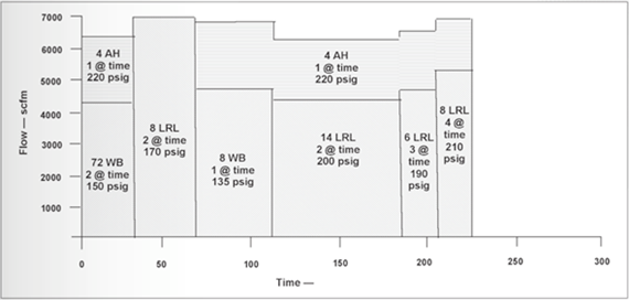
“Stacking Considerations” – Operating Parallel Blowers When Possible.
It is poor practice to blow in the pendant reheat surface at the same time the wall blowers are in use. The control system can be arranged so this will never occur. Blowing an air heater at any time usually has no disturbing effect on the boiler, nor does blowing any horizontal boiler surfaces, which usually includes primary reheater, superheater, and economizer surface.
The concept of “stacking” which helps to level load the compressed air system may create some problems for the boiler, with significant temperature excursions. Larger boilers would experience much lower magnitude of upsets. Pressure requirements vary greatly from lance to lance. Normal ranges are from 135 to 260 psig at the nozzle of the blower. Pressure is related to the cleaning energy (PIP) required for a given area and cooling requirements.
Cooling long retractable lances in higher temperature areas of the boiler use a substantially greater quantity of air for cooling than for cleaning and at a higher pressure. A high pressure for the long retractable lances is often required to accommodate the pressure drop associated with the high flow rates and long lengths of the blowers. Typical cooling requirements for long retractable lances are:
| Lance Length | Approximate Cooling Requirements |
| 40 ft. | 6,000 scfm or more |
| 50 ft. | 9,000 scfm or more |
Required compressor pressures are normally conservatively picked to account for large pressure drops through the piping system and control valves of the soot blowers. The overall pressure drop may be as high as 100 psig from the compressor discharge to the soot blower nozzle. Approximately 50 psig maybe lost in the control valve at the entrance to the lance. This is often recoverable.
Wall Blowers or IR Blowers
Wall blowers are used to clean the furnace walls and will probably use approximately 2,200 to 2,300 scfm. Wall blowers normally operate in one or more pairs depending on the overall cycle. Their basic job is to reduce slag that has accumulated on the pipes in the upper levels of the boiler, and superheated region. When the slag builds up on the pipes the rate of heat transfer decreases, this will lower the temperature of the steam going to the superheated portion of the system, therefore decreasing overall efficiency of the system.
A normal cycle for a wall blower starts when it energizes and moves out into the furnace to its outermost position where the control valve opens and air starts flowing. It takes three seconds to go from zero to full flow. The wall blower rotates one or more times depending on the amount of cleaning required and then the control valve closes in three seconds and the blower retracts into the wall.
The time for a wall blower cycle is approximately three to six minutes and the period of zero flow between wall blower flow to no-flow to flow can be as high as 1 _ minutes in a normal sequence. This may be reduced if cycle time needs to be reduced by overlapping.
Long Retractable Lances or IR Blowers
Long retractable blowers are used to clean pendant-type radiant surfaces and convection surfaces in high temperature zones as well as convection passes to reduce slag buildup on the walls of the boiler and for temperature control. These areas are normally in the super-heater, reheater, and the economizer section.
The long retractable lance cycle starts when the lance energizes and extends into the boiler and air starts flowing with the three-second delay from the control valve. The lance travels outward and rotates at the same time. The linear speed varies from 65 to 150 inches per minute, depending on the cleaning and temperature zone requirements.
Long Retractable Lance Cleaning Pattern
Long retractable lances vary in length with the boiler size and are one-half the width of the boiler. Cooling is very critical with these lances since they may operate in temperature zones up to 2,000_F and are cantilevered out from the side of the boiler walls.
Air Heaters
The long retractable blowers are often also used in the air heater section. Sometimes a “swing arm” type blower may be used in the air heater section. This will use a lower magnitude of compressed air, but will generally require a longer cycle.
System Interlocks
Several safety interlocks can be provided on soot blowing systems. One or more of the interlocks listed below may be used:
These safety interlocks are used to prevent damage due to low air pressure or flow to the lances, especially the long retractable lances while they are operating in the boiler.
The loss of a lance will reduce boiler efficiency and eventually will lead to a plant shutdown.
For more information please contact Hank Van Ormer.


