Audit of the Month |
|||||||||||||||||
|
|||||||||||||||||
|
|||||||||||||||||
|
|||||||||||||||||
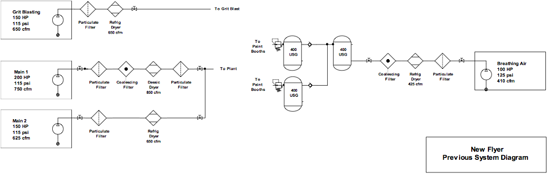
| Summary of System Before the Audit: Four plant compressors operating as three independent systems. All four required during normal production time in order to maintain adequate pressure. Air dryers were a mix of desiccant and refrigerated. | |||||||||||||||||
|
|||||||||||||||||
| Summary of System After the Audit: One large compressor retired to standby duty. A new VSD compressor added. Compressors run as a combined system. Trim compressors used to supply higher pressure to pressure critical loads on the upstream side of an intermediate controller. Main plant pressure reduced. Dryers converted to cycling style. Heat of compression recovered to heat plant in winter. |
Introduction
New Flyer Industries is a Winnipeg based heavy duty bus manufacturer, supplying vehicles to the US and Canadian markets. The company specializes in vehicles with†alternative-fuel drives such as electric trolleys, gasoline-electric and diesel-electric hybrid vehicles; as well as standard diesel buses.
A few years ago New Flyer’s facility manager requested a compressed air system audit to solve a number of issues challenging the plant maintenance and production personnel. The plant was experiencing regular low pressure events that affected painting activities and disrupted the plant production schedule. Maintenance costs were high and system reliability was in need of improvement. New Flyer was also interested in reducing facility energy consumption and was aware that compressed air systems represented a good potential energy reduction opportunity. Their plant equipment was aging and the company was interested in upgrading their air system using the local power utility’s financial incentives for energy efficiency upgrades. The utility required a feasibility study be done to qualify.
Manitoba Hydro was retained to do a study of the compressed air system and to recommend improvements. This article discusses the study and some of the results of the completed project.
Supply Side Audit
The facility operates as an automotive assembly line with compressed air being required on a 24 hour - 7 day a week (8,760 hours) basis to feed various plant operations. The average electrical rate at this facility is \$0.0259 per kWh with a demand charge of \$7.08 per kVa per month. Based on these rates the average blended power cost is \$0.0356 per kWh.
Data loggers were placed on the facility compressors for a number of weeks to determine the compressed air energy consumption and to help construct air usage profile. The logging and site observations found that the four existing air compressors were operating as three independent systems. The audit found that the total compressed air energy consumption, including air dryers, was 2,218,000 kWh per year while producing an average of 700 cfm. This calculates to an average system specific power of 36 kW/100 cfm. This benchmark showed that system efficiency was poor and that significant improvement potential existed.
 |
System 1 – Main system
System 1 supplied the main plant air using one 200 HP modulating compressor (with capacity control) through a fixed cycle desiccant air dryer. A second 150 HP compressor running in modulation mode fed air to the plant during high demand periods. This smaller unit had an associated refrigerated air dryer.
Monitoring and testing of the supply equipment in this system showed the following issues:
The 200 HP compressor controls were set up incorrectly. The unit used spiral valve capacity control and inlet modulation to control the output of the compressor, however, the capacity control was not operating correctly, greatly decreasing the efficiency of the unit. The unit was flow tested and was found to be producing 83% of its full load capacity.
The main system was experiencing low pressure events caused by peak air flows that exceeded the capacity of the two compressors. Plant pressures were dropping below 85 psi which shut down plant equipment and machines.
The 900 cfm desiccant air dryer was malfunctioning and consuming 220 cfm of air or 25% of its nameplate rating.
The dryer filters were causing a high pressure differential which prevented the compressors from fully loading during times of high air demand.
Compressor coordination issues caused the 200 HP unit, the most expensive unit to run, to run constantly, even during lightly loaded evening and weekend shifts. This unit had no automatic blow down control.
The refrigerated dryer was operating in non-cycling mode causing it to run even when the associated compressor was turned off.
 |
||
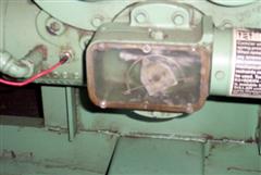
| Capacity Controls like this are controlled by a simple screw driver adjustment. Incorrect adjustment can greatly affect the efficiency of the compressor. |
System 2 – Blasting System
This system consisted of a 150 HP compressor and refrigerated dryer set up an independent supply for a grit blasting operation used to clean bus frames. This compressor was installed with no storage and was operating using inlet modulation control with pressure switch unloading. The unit was equipped with the auto-dual option which is designed to unload and even turn off the compressor during light loads, however, because the system had no storage capacity, the compressor ran constantly, rapid cycling between loaded and unloaded operation even though blasting air was required only 15% of the time. Data loggers showed that this compressor was lightly loaded during times when the main system was starved for air making it a good potential source of extra capacity during peak flows.
System 3 – Paint line and Breathing Air
Due to the pressure problems in the plant, the plant paint lines were split off the main plant system at some time in the past and fed by a separate independent 100 HP load/unload compressor. A 400 gallon storage receiver was installed, but due to its small capacity and a high pressure differential across the system filters and refrigerated air dryer, the unit rapid cycled causing it to consume significant power even though the system was on average lightly loaded at about 20% capacity. Two other check valve protected storage receivers were installed to protect the painting lines against momentary low pressure events. This was working correctly. This air system was also a potential source of extra air during peak loading.
End Use Audit
As part of the audit a review of the various plant compressed air uses was done to determine if there were any opportunities for compressed air demand reduction. This is a time consuming but necessary process that is essentially a thorough point-by-point review of every end use that is connected to the compressed air system. Each use is assessed for possible performance improvements and/or compressed air use reductions. A number of opportunities were found:
- Paint booth filters and compressed air piping were undersized causing excessive pressure drop. This caused the painting operations to be more sensitive than normal to plant pressure fluctuations and forced the plant pressure higher, causing higher compressor energy consumption.
- Grit blasting nozzle maintenance was less than optimum. Allowing the nozzles to wear excessively before replacement causes higher than desired compressed air consumption, adding to the plant pressure problem at peak flows.
- Open pipe air wands were being used to clean away the blasting media from the bus frames after blasting. These wands were deemed to be a safety hazard as they did not have dead-man switch control, generated excessive noise and wasted compressed air, causing higher than desired peak flows.
- Air winches were being used to move the assembly line. These large air motors were found to use about 10 times the energy of an equivalent electric motor.
- Breathing air purifiers, essentially a desiccant air dryer with a catalytic converter element on the back end to remove any dangerous carbon monoxide from the breathing air supply, were found to be running constantly, even during evenings and weekends when painting operations were not in operation.
 |
||
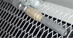
| Blast nozzle erosion of even 1/16th of an inch can increase the air consumption by 30%. A 10 psi plant pressure increase will increase the air consumption by 9%. |
 |
||
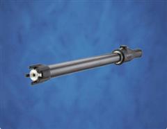
| An engineered nozzle like this is safer, uses less air and much quieter than a typical pipe style air wand. (Source www.silvent.com) |
Study Findings
The New Flyer plant had at one time used a single combined system to supply the total plant requirement, however, because very large peak flows demanded by media blasting operations were found to be pulling down the main system pressure, a separate compressor was set aside to feed part of these peak flows in an attempt to protect the main system pressure. Further to this, when air pressure problems continued, the pressure critical painting line was separated off the main system with a new dedicated compressor.
The compressed air audit revealed that separating the systems solved pressure problems in critical localized areas, but the result was the total system ran very inefficiently. In almost all cases three separate screw compressor systems will consume much more power than one single well controlled system. This is because each of the three separate systems will now have at least one compressor operating at partial load (a trim compressor). And in air systems with standard fixed speed screw compressors, it is the trim compressors that cause the inefficiency, due to their inherently poor part load efficiency.
Analysis of the flow profile of the plant showed that the original plant pressure problems were likely caused by poor compressor control and the lack of system capacity. Basically the plant pressure dropped to low levels because the peak plant load (during media blasting) exceeded the capacity of the existing compressors. With the addition of a single 100 HP VSD compressor, coordination of compressor controls, and some load reduction, primarily through elimination of desiccant air dryer purge, pressure reduction, and reduction of blowing events, the study showed the three systems could be combined into one well performing system with enough capacity to handle the full plant peak load with no pressure issues.
New System
To achieve the proposed savings New Flyer consolidated their existing air system by combining all of the existing compressors into one single system. The existing 200 HP compressor was retired to standby duty with the intention to run it only on failure of one of the existing units. Once the poorly performing desiccant air dryer was eliminated, and the three systems were combined, only 100 HP of extra compressor capacity was required to maintain plant pressure during peaks. This new 100 HP VSD compressor was selected to match an existing 100 HP fixed speed unit and together the two units provide 200 HP of efficient trim capacity pumping into a new 3,000 gallons storage receiver.
 |
Because the paint line requires higher pressure than the main plant, the supply to the line is taken from the high pressure side of an electronically controlled intermediate controller that regulates the main plant pressure at precisely 105 psi. The base 150 HP compressors have been placed on the downstream side of this intermediate controller, reducing their discharge pressure, and lowering power consumption. These units have been set to operate within a single pressure band that brackets the set point of the intermediate controller using a sequencing system internal to the compressor controls.
The new system is performing well with the 200 HP of trim capacity easily and efficiently handling the average plant load. The 150 HP base units are now required only when media blasting occurs, which is about 15% of the time. With the new reduced load and the more efficient compressor operation, the system energy efficiency increased with the combined system consuming an average of 124 kW (including air dryers) while producing an average flow of 490 cfm. This calculates to a more respectable 25 kW per 100 cfm system specific power.
All air dryers have been converted to cycling style, with the refrigeration systems now running only when required, in response to actual dryer moisture loading. Dryer filters have been converted to mist eliminator type with the low pressure differential making compressor control more efficient and reducing the required compressor discharge pressure, which lowers power consumption.
The trim compressors are located internal to the plant which means heat of compression can now be used in winter months to displace natural gas heat. Based on current plant loading, this is saving New Flyer about 36,000 cubic metres of natural gas worth \$12,000 annually at current costs and reducing greenhouse gas emissions.
Maintenance Reductions and Plant Reliability
Previous to the project the plant maintenance personnel could not take any one compressor down during the normal production day without risking plant pressure problems. This meant that regular compressor service had to be done during weekends or at night where maintenance costs were a premium. And when disaster happened, and a compressor would fail, production would be affected, necessitating the emergency rental of an expensive diesel compressor.
The new system now has the capacity to provide adequate plant pressure with one compressor out of service. This significantly reduces maintenance costs and decreases the frequency of plant pressure issues.
Utility Incentives
The New Flyer plant is located in an area of North America serviced by Manitoba Hydro, a utility generating electricity primarily using renewable water powered generation. Typical of hydro power producers, the power prices are quite low compared to other areas in North America. This is of great benefit to customers, however, from an energy efficiency point of view it makes energy projects more difficult to sell based on energy savings alone. Fortunately, Manitoba Hydro was able to provide a substantial financial incentive though their Power SmartÆ Performance Optimization program. This program was able to provide enough support to bring the project payback to 1.5 years, within the acceptable payback range for management acceptance.
Facility Management Speaks
“This project was very attractive because it fit in with our Corporate goals supporting safety and the environment.” says Tino Della Valle, New Flyer’s Manager of Facility Engineering and Maintenance, who was in charge of the air system upgrade, “And our compressed air system downtime is no longer an issue. From the point of view of production, the compressed air system performance is now quite invisible to our users.”
“It’s nice to be able to renew our equipment and get excellent system improvement at the same time, and with Manitoba Hydro helping out with their incentives, it was like purchasing the equipment at a 50% discount.”
Conclusion
This project is an excellent example of how getting to understand the system through an air audit can yield excellent results. Analyzing the system can often find solutions to problems that will reduce energy costs, and increase system reliability cut maintenance requirements. Savings and benefits of the project can often be used to justify and pay for equipment renewals. And it shows how utility incentives can help drive projects that may not normally be approved by management.
For more information contact Ron Marshall, Marshall Compressed Air Consulting, tel: 204-806-2085, email: [email protected].
To read more articles about the Transit Industry, visit www.airbestpractices.com/industries/transit.


