The System Assessment Objective
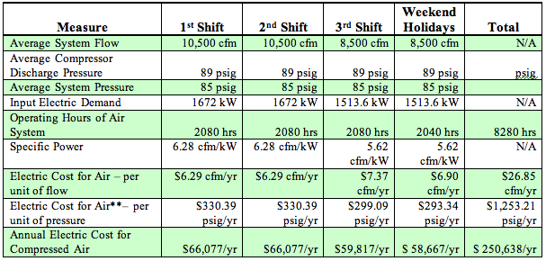
This northeastern U.S. automotive manufacturing facility spends \$269,046 annually on energy to operate their compressed air system. This figure will increase as electric rates are raised from their current average of .019 cents per kWh. The set of projects, in this system assessment, reduce these energy costs by \$110,166 or forty percent. Reliability of compressed air quality, however, is the main concern in this plant and the primary focus of this system assessment.
Due to space limitations, this article will focus on the air quality and demand-side projects recommended to ensure a -40 F pressure dewpoint in the compressed air system - while reducing over-all demand by almost 4,000 scfm.
The Baseline: Supply-Side System Overview
The full load operating range is 345 days a year, 24 hours a day, 8280 hours a year. There are two flow meters in the system and the modicom central system monitors the percent load of each unit continuously.
The load profile or demand of this system is not relatively stable during all shifts. The total plant compressed air requirement observed was 13,500 to 15,000 cfm peak flow, a 8500-9,500 cfm minimum flow and an average flow of 10,500 cfm. These numbers were established through interviews with plant personnel, reviewing historical flow recordings and observing the loads on the modicom system. The central modicom control system appears to control and monitor all seven compressors very well.
During the system assessment, we were informed of plans to increase compressed air demand by 1200 cfm due to the installation of an additional four (4) molding machines.
| Compressed Air Flow Scenario | Flow (cfm) |
| Current maximum possible peak demand (rarely seen) (including current expansion mold and bead blast) | 19,000 to 20,000 cfm |
| Current peak demand usually observed | 13,500 – 15,000 cfm |
| Average production flow (with 4 new mold units) | 10,500 – 11,700 cfm |
| Low production demand | 8,500 - 9,500 cfm |

This plant has two separate air compressor rooms. Compressor Room #1 has five (5) double-acting reciprocating air compressors able to provide a total nominal 15,000 cfm. The air is sent to one glycol chiller refrigerated air dryer (reported to be rated for 9000 cfm flow). Compressor room #2 has two (2) double-acting reciprocating air compressors able to provide a total nominal flow of 6,000 cfm and one (1) “chiller air dryer” rated for 15,000 cfm).
Each compressor room has a 12” compressed air line header. Basically, there are two compressed air distribution systems. There is one 8” interconnecting line between the two systems.
The plant has condensate problems in the system and many (46) heatless desiccant dryers have been installed throughout the system at point of use. It is estimated that the purge air, required to regenerate the towers, is creating a demand for 3,000 scfm of compressed air.
All existing compressors are positive displacement, two stage reciprocating and 3000 scfm class capacity each. From a total of seven (7) compressors, five (5) can be in operation at any time. One compressor is stand-by and one is usually off line.
The primary compressors are efficient air compressors that are capable of delivering 90 psig full load pressure. The primary compressors are very well maintained, very well installed and very power efficient units at both full and part load. They are lubricated type. Most important, they are very old – particularly the three units in Compressor Room #1. These are late 1940’s units, well over 50 years old and have been out of production for over 35 years. It is difficult and expensive to obtain any major parts when and if needed. There may still be some used parts in the gas fields but certainly not any left on the used equipment lots.
The reciprocating compressors are double-acting, water-cooled units with five-step unloading. This is an efficient compressed air unloading system. Reciprocating five-step unloading will efficiently translate the percentage reduction in air usage of “less air used” into nearly the same proportional reduction in energy cost. The older three “late 1940’s units”, however, overheat if run at 25% of load.
The other four units are not quite 25 years old and are no longer manufactured in the United States. There is limited production overseas and critical parts are available – some at long lead times. There are 10” stroke models with many parts available in the used equipment lots now but as time goes by they will end up in the same situation as the older units. The plant is spending significant resources on periodic overhauls, maintenance, and water-cooling for these air compressors.
Cooling water, for the air compressors, is supplied from three sources; mill water (a settling pond of recycled water), process water (treated and filtered water) and cooling tower water. The older three air compressors in Compressor Room #1 use process water for inlet and head cooling and mill water for the inter and aftercoolers. The other four air compressors and aftercoolers are on cooling tower water.
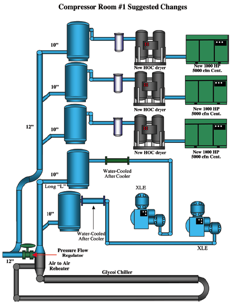
This article does not have space to review the supply-side recommendations. We did recommend replacing the older three recips with three new oil-free centrifugal air compressors piped to heat-of-compression dryers in Compressor Room #1. The energy savings were not significant- the benefits were improved air quality and reduced maintenance and water-cooling costs. The project also recommended replacing the refrigerated dryer in Compressor Room #2 with a blower purge desiccant air dryer the company could transfer in from another facility.
The Baseline: Current System Key Characteristics
Demand-Side Projects to Reduce Compressed Air Consumption
The overall strategy for improving the air system centers on repairing purge controls on compressed air dryers and reducing overall demand. The recommended projects include:
| Air Flow Reduction Projects | Air Flow Savings |
| Eliminate purge air from 46 heatless desiccant dryers | 3000 cfm |
| Repair compressed air leaks | 200 cfm |
| Replace timer drains with demand drains | 47 cfm |
| Replace ten air operated diaphragm pumps with electric | 320 cfm |
| Total Compressed Air Flow Reduction | 3,567 acfm |
Project #1: Air Dryers and Dewpoint Monitors
One of the higher air users in the plant and the largest air user in molding is the X line, which is still growing. Plant personnel have done a great deal of investigation in modeling the air flows to this system and have collected some very significant data. This acquired data allows for effective analysis and developing solutions to continue to improve quality and productivity.
Reviewing this data and showing the changes already implemented and to be implemented, leads us to believe that this process is being very well handled and will continue to evolve to its optimum performance level. The 8” header appears to be supplying air appropriately and the larger planned feeds should eliminate any pressure loss problems, particularly when the point of use dryers are out of the circuit.
The large supply receivers already installed should effectively isolate the system even without pressure flow regulation.
Molding uses both “wet air” and “dry air” – systems that can be combined into one when an effective central compressed air drying system is in place. It is important to note that when we reviewed the molding operations, we saw the heatless point of use dryers in many operating modes:
- Dryers at full capacity with purge air
- Dryer turned off but still in the flow – still using purge air.
- Dryer turned on but valved out of the flow
- Dryer turned off and valved out of the flow
Bead blast is another high consumer of compressed air. Most of these units are blast cabinets with robots handling the pieces that are blasted with precisely controlled compressed air. Control air is critical and apparently higher pressure (80-90 psig) and the blast air pressure indicated on the machines ranged from 35 to 50 psig. Often with a 50 psig setting, the actual feed pressure at work runs at 40 psig.
We believe that since this is such a high use item and requires high quality dry air for a sensitive process, that the plant should review and analyze the relative dynamics. A closely monitored and precisely measured program similar to what you have and are implementing at the “X Line” will generate excellent opportunities for improvement and savings.
After the (2) new 400 scfm heatless desiccant dryers are installed in front of the new molding machines, there will be at least 48 heatless type desiccant dryers installed throughout the system. We observed several dryers valved out of the system (in bypass) while the production machines were running. The dryers were not drying the air to the system – but many were still purging air. These dryers (some have “dewpoint demand control”) collectively use about 3000 scfm of purge air. This costs the plant about $75,750/yr in electric power to produce this 3000 scfm of compressed air.
These desiccant dryers are required, throughout the plant, because the supply-side refrigerated dryers cannot provide the required dewpoints. The chiller dryer (in Compressor Room #2) was rated to handle 15,000 scfm of air at 100°F/100 psig and deliver a +40°F pressure dewpoint. However, in reality, this technology is basically limited to a + 50°F pressure dewpoint consistently at 89 psig.
The glycol cooler/reheater arrangement in Compressor Room #1 has delivered a measured +39°F pressure dewpoint in the past. It’s performance is very dependent on what cooling water temperature it receives and the performance of the water-cooled after-cooler on the compressors. Plant personnel are not sure of the full rating on this dryer but feel it may be limited to handling 9000 scfm effectively.
By modifying the supply-side air treatment to include heat-of-compression dryers in Compressor Room #1 and a blower purge desiccant air dryer in Compressor Room #2, the plant will ensure air quality throughout their processes. This will allow the plant to remove and/or bypass all the decentralized heatless desiccant air dryers and can reduce their compressed air consumption by 3000 cfm.
Project #2: Air Leak Identification and Repair
Leak levels, in most plants, represent 20% of total compressed air demand. Fifty leaks were identified in this plant. We estimate 4 cfm of wasted compressed air per leak for a total air flow reduction opportunity of 200 cfm.
| Estimated number of leaks | 50 leaks |
| Estimated average leak size | 4 cfm/leak |
| Estimated reduction of air flow with proposed project | 200 cfm |
| Current air flow cost | $22.98/cfm year |
| Annual electric cost savings with proposed project | $4,596/year |
| Unit cost of leak repairs | $2,500 |
Project #3: Replace Timer and Manual Condensate Drains with Level-Operated Drains
This project focuses on replacing all timer and manual condensate drains with level-activated electric or pneumatic-actuated automatic condensate drains. Dual timer electronic drains use an electronic timer to control the number of times per hour it opens and the duration of the opening. The theory is that you should adjust the timers to be sure that the condensate drains fully and the open time without water is minimized, because it wastes compressed air. The reality is that the cycles either don’t get reset from the original factory settings (which causes condensate build-up in the summer) or they get set wide open and not closed down later in cooler weather, thus wasting more air. When they fail “stuck open”, they blow at a full flow rate of about 100 cfm.
Consider, for example, that the usual “factory setting” is 10 minutes with a 20-second duration. 1500 scfm of compressed air will generate about 63 gallons of condensate a day in average weather or 2.63 gallons per hour. Each 10-minute cycle will have 0.44 gallons to discharge. This will blow through a ¼-inch valve at 100 psig in approximately 1.37 seconds. Compressed air will then blow for 18.63 seconds each cycle, 6 cycles a minute will equal 111.78 seconds per hour of flow or 1.86 minutes per hour of flow. A 1/8-inch valve will pass about 100 cfm. The total flow will be 100 x 1.86 = 186 cubic feet per hour, or 186 * 60 minutes = 3.1 cu ft/min on average. This 3.1 cfm would translate into an energy cost of \$300 per year based on a typical air flow cost of \$100 per cfm year. In reality they are often set much longer generating higher values.
Level operated electronic drains come in a number of varieties, including ones that receive the signal to open from a condensate high level and the signal to close from a condensate low level. These waste no air and from a power cost standpoint, are the best selection.
The system assessment identified fifteen drains that should be replaced.
| Total of number of drains | 15 |
| Air flow (cfm) savings per drain | 3.1 cfm |
| Total compressed air saved | 46.5 cfm |
| Estimated energy savings per drain | $71.24/year each |
| Total annual savings | $1,069/year |
Project #4: Air-Operated Diaphragm Pumps
Although air-operated diaphragm pumps are not very energy efficient, they tolerate aggressive conditions relatively well and run without catastrophic damage even if the pump is dry. There are several questions to ask and areas to investigate that may yield significant air savings:
- Is an air-operated diaphragm pump the right answer? An electric pump is significantly more energy efficient. Electric motor driven diaphragm pumps are readily available. An electric motor drive progressive cavity pump may also work well.
- Consider installing electronic or ultrasonic controls to shut the pumps off automatically when they are not needed. Remember that pumps waste the most air when they are pumping nothing.
- Is the pump running most of the time at the lowest possible pressure? The higher the pressure is, the more air is used. For example, filter packing operations often do not need high pressure except during the final stages of the filter packing cycle. Controls can be arranged to generate lower pressures (and cycles) in the early stages and higher pressures later on -- which may generate significant savings.
The system assessment replaces (10) air-operated 1 ¼” diaphragm pump in coating with electric-driven unit on units running light fluid and continuous run.
| Air flow associated with air-operated pump (80% utilization) | 32 cfm avg |
| Current air flow cost | $22.93/cfm |
| Annual electric cost to operate air-operated pump | $735/year/each |
| Electric demand of new electric pump | .75 kW (average) |
| Annual electric cost to operate electric pump | $118/year |
| Annual electric savings | $617/year/each |
| Annual savings for replacing (10) pumps | $6,170 /year |
Conclusion
The primary results of this system assessment were to modernize a portion of the air compressors into oil-free centrifugal technology able to use heat-of-compression dryers. This allowed the factory to reduce the significant maintenance and water cooling costs involved with the long-lasting and efficient double-acting reciprocating air compressors. The new supply configuration also allowed the factory to eliminate the small army of heatless desiccant air dryers that were purging 3,000 scfm or compressed air.
For more information contact Hank van Ormer; tel: 740-862-4112, www.airpowerusainc.com.
To read more System Assessment articles, visit www.airbestpractices.com/system-assessments.


