So you need nitrogen in your plant! In a high percentage of cases, generating your own nitrogen using commercially available equipment is a very cost effective alternative to purchasing liquid nitrogen or cylinder nitrogen from traditional supply sources like the industrial gas companies. In some cases, the return on investment (ROI) ranges from six months to 2 years, but ROI can range, depending on several factors, to several years while still being a good investment. With rising fuel and energy costs, the cost of liquid nitrogen is going up and is making it much easier to justify the purchase of a nitrogen generator in a wide range of purities and pressures.
If you are considering purchasing a nitrogen generator for your facility, you may be in luck. The first question to settle is what nitrogen purity you actually need for your application and facility. Nitrogen purity is generally expressed as a percent, such as 99% Nitrogen (which means 1% Oxygen with the balance nitrogen and other inert gases). In some high purity cases, it may be expressed as PPMv Oxygen remaining in the product gas. 10 PPMV is the same as 99.999% nitrogen. 10,000 PPMv equals 1% O2. The answer to the purity question can make or break a project’s budget, and have a huge impact on the amount of electricity used. There are many factors to be considered. First there are some basic dynamics common to self generated nitrogen gas that should be considered.
About the Technologies
There are actually four main processes to generate nitrogen on site; the old traditional air separation process where large volumes of compressed air are pressurized to a high pressure (several hundred PSI) and quickly expanding to at or near ambient pressure, through several stages of recirculation, compression, and expansion to liquefy the various constituents of air such as nitrogen, oxygen, argon primarily. Other rare gases are also liquefied at the same time. Each of the gases liquefies at a given cryogenic temperature. These systems are usually for customers who need high purity and use greater than 20 tons of nitrogen per day and are typically leased from an industrial gas company. There are some companies around that design, build and sell turnkey on site cryogenic plants.
In some cases, using a catalyst in conjunction with lower purity nitrogen from a membrane or PSA is used to achieve extremely low oxygen levels in the nitrogen gas, called De-Oxo, but is used rarely and will have some level of hydrogen gas in the nitrogen product. It is used to keep the compressed air requirement lower than say a PSA at 99.9995%, but the system is more complicated.
For the purpose of this article, we will focus on the two non-cryogenic methods of producing nitrogen gas; Pressure Swing Adsorption (PSA) and Membrane. Both of these technologies use compressed air as a feed stock in the production of nitrogen.
Pressure Swing Adsorption (PSA) uses, in most cases, two vessels, packed with carbon molecular sieve (CMS). The CMS adsorbs Oxygen as compressed air flows upward through one of the vessels while the other vessel is depressurized and a small amount of the nitrogen output is flowing downward (counter flow) to drive off or desorbs the oxygen and moisture collected by the vessel when it was online removing oxygen from the air. The vessels alternate this adsorption and desorption process. There are several steps in the process; equalization, pressurization/depressurization, adsorption/purge, then back to equalization. This is a basic description of the process, but there are several things happening at various times throughout the time cycle which is generally a 2 minute cycle total. PSA generally takes up a little more floor space and is a little noisier than most membrane systems. It requires in most cases an air buffer tank, nitrogen buffer tank, and sometimes is sold without the air purification system that is critical to the protection of the CMS beds. PSA is generally offered for sale using a 125 PSI air compressor, common to most plant air systems. PSA technology is generally used where higher purities are needed, and in many cases if the system is very large in capacity. Over the last 10-12 years, there have been many advances in the production of both membrane and pressure swing adsorption (PSA) technologies. Flow improvements in carbon molecular sieve (CMS) used in PSA equipment has shown approximately a 60% increase in flow rates and air to nitrogen ratios have come down dramatically.
Membrane systems use hollow fibers of man-made polymers, of various lengths, diameters, materials, and efficiencies to use differential pressure in a process known as selective permeation to separate the gases from the compressed air stream. Sometimes millions of these hollow fibers are packed into a vessel and are referred to as membrane bundles, or just membranes. The membranes are generally installed in parallel with each other to provide the needed capacity. The device uses the semi-permeable fibers to allow faster gases to quickly permeate the walls of the fibers and released to atmosphere. Faster gases are mainly oxygen, carbon dioxide, hydrogen, and water vapor. There are no moving parts to the separation process, which is attractive from a maintenance and simplicity standpoint. The systems require other components which do have moving parts as well as other electrical controls to make the system functional. Most industrial systems also have an air circulation heater which adds to the kW consumption of the system. The systems generally take up a small footprint and in most cases, very quiet. If they are not quiet, the wrong membrane was used or the piping and components are severely undersized to keep costs and footprint at a minimum.
There are currently only five companies manufacturing membranes and each has its own design variations. Among these variations from the manufacturers are their air-to-nitrogen ratio (ANR) sometimes expressed as the inverse of ANR called recovery (percentage of nitrogen to the total air consumed. Other differences are the fiber materials, diameters, pressure drop characteristics, degree of sensitivity to oil vapor, physical size, pressure ranges, temperature ranges, production efficiency, energy efficiency, and range of model selection, overall quality and cost. Each manufacture has is unique advantages and disadvantages when compared to each other. They are not all the same, by any means and as this article will demonstrate the selection process will make a huge impact on, not only the capital cost, but more importantly the life cycle operating cost which is primarily the electricity to run the system.
Some membranes, with the emphasis on SOME, can reach purities approaching that of a PSA, but they cannot do so economically or reliably. These membranes are put in series, two or three stages, creating a very high pressure drop across the system and are extremely inefficient and cost much more than a PSA at the higher purities. To keep capital costs competitive, membrane systems are usually quoted using a 150-200+ PSI air compressor, because a membrane will produce more nitrogen flow at a given purity at higher pressures. Membrane technology is generally used when purities required are 99% or lower and some are not efficient at that purity. Other reasons for choosing a membrane generator are portability, flexibility in system design for special space considerations, and they are simpler to understand the process and maintenance is generally simpler.
Both technologies use essentially the same filtration that requires essentially the same level of maintenance. PSA units have several valves that will leak at some point over the years and require routine maintenance. These leaking valves will cause the purity to fall off abruptly, so there are some maintenance considerations not found in membrane systems. In either case, the heart of both technologies, the membrane fiber or the carbon molecular sieve (CMS) must be protected from water, particulate, oil and in almost all cases, oil vapor. Regular filter maintenance must be performed or the nitrogen purity will decline to the point where the system is not fit for its purpose, costing a large percentage of the initial cost of the nitrogen generator to bring the system back up to original specifications. The compressed air purification system should consist of tank(s), aftercooler, water separator, air dryer (selected carefully for the application), and multi-stage particulate and coalescing filters and carbon bed, all designed to meet the unique needs of the membrane brand or PSA system.
Nitrogen Use in Food Processing & Packaging – Webinar RecordingDownload the slides and watch the recording of the FREE webcast to learn:
|
The Energy Cost per SCFM of Your Nitrogen Specification
The higher the percent nitrogen required, the larger the system to obtain a given flow rate. More compressed air will be required and more electricity consumed. Capital cost, long term maintenance cost, and floor space will increase as well. Whereas, a 95% N2 system will take approximately 2 SCFM of compressed air for 1 SCFM of nitrogen, the ratio of air to nitrogen could be as high as 12:1 at 99.999% N2 in some older systems. Here are a few “Rule of Thumb” Nitrogen specs for some industries (For Comparison Only)
- Blanketing to prevent hazardous conditions – Approximately 95-97% for most applications
- Blanketing edible vegetable oils – approximately 99.9%
- Food Packaging – approximately 99.5% for most applications
- Printed Circuit Boards – Traditionally has been in the 99.9%+ range, but long term testing shows that this application can be done at 97% with no visible or long term effects.
- Heat treating metals – Depending on materials and process, can be 97% to as High as 99.999% (10 PPM of O2)
The bottom line here is that most nitrogen systems are “over spec’d” because the information is sometimes hard to obtain and so to be safe, consumers will often specify a higher purity of nitrogen than they need. Sometimes this comes from an equipment manufacturer, who has not done sufficient testing at various nitrogen purities. In the earlier days of nitrogen generators, this information was difficult to come by, but over the years more and more application specific information has become available. This can sometimes be obtained through industry associations and from equipment suppliers, and industry professionals. Another valuable source is from your own employees who may have worked in a similar job in the past and can tell what purity worked at their former company.
Using Nitrogen in Place of Compressed Air – Should you or Shouldn’t You?
Many companies use nitrogen when they don’t need to. Because nitrogen is a very dry gas, it is sometimes used in place of dry compressed air. At steady state conditions 95% N2 is around -85oF Atmospheric Dew Point (5.3 PPMv Water Vapor). 99.5% N2 is below -105oF (<1 PPMv). It is enticing for companies to use nitrogen in place of air; but at what cost? Below are a couple of reasons consumers use nitrogen in place of clean, dry compressed air; one possibly justified, the other a very costly practice.
In one example a company has experienced problems with compressed air quality due to a variety of reasons. Usually, however, a properly applied air dryer, the correct selection of filtration combinations, choosing a dew point suitable for the application & ambient, and having properly maintained equipment will be as reliable and certainly much more cost effective than using nitrogen gas. The user will use at least 1.8 times as much air to produce the nitrogen and you have to dry and filter the air to the nitrogen generator with greater emphasis on purification design than is generally needed for the plant. It is just not a good idea. Use a qualified compressed air professional to solve this problem using compressed air.
There are companies using nitrogen at multiple locations throughout the plant and only a small amount of air for pneumatics. The system might be simplified having a single piping network using nitrogen. In this example, a case could be made FOR the use of nitrogen in lieu of compressed air, as long as the nitrogen purity required is fairly low; i.e. 95-97%, and usually if an extremely low dew point is required for the facility. This should be thoroughly thought out, weighing the pros and cons before using nitrogen in place of compressed air.
Energy Cost Implications Based on Varying Nitrogen Purities
Table 1 below compares a high flow, low purity membrane (HFLP), a high purity lower flow membrane (HPLF) and pressure swing adsorption (PSA) type nitrogen generators. Due to the wide disparity in membrane performance among the five manufacturers, I chose a low and a high range for an overall comparison. This is not an effort to push PSA over membranes. There are many applications where membranes are a great choice. One just needs to know the limitations of each and apply the technology that best fits the application’s requirements. In the tables there are some abbreviations that need to be defined here. SCFM N2 is an arbitrary flow rate used for the basis of these examples. SCFM is nitrogen and air flow at atmospheric conditions that the nitrogen and the compressed air manufacturers use as their standards. The standards may vary a bit, one to another, but they all come back to some ambient condition, so we will not get into conversions in this article. The safety factor applied to the air required will cover these minor differences. ANR is the air-to-nitrogen ratio. This is the measure of the efficiency of the technology. Multiply this number by the N2 SCFM to get the SCFM Air required. CCF is the Compressor Correction Factor. Size the compressor 1.25-1.3 times the required compressed air SCFM to allow for winter/summer ambient, variations in membrane performance, flow unit conversion, as well as the compressor manufacturer’s flow tolerance. Do not go below this number. Some manufacturers recommend a 1.3 CCF. Over the years, I have used the 1.25 and this number has worked well for me.
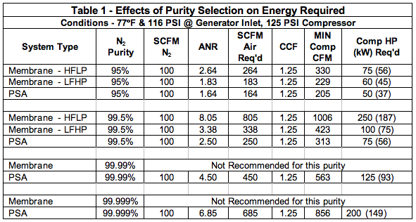
In Table 1, one can see how drastically the effects of the purity chosen for the 100 SCFM nitrogen example. The compressor horsepower ranges from 50 to 250 depending on things like the technology used, the purity percentage of the nitrogen.
Compressed Air Purification & Piping Monthly e-NewsletterWith a focus on Demand-Side Optimization, compressed air dryers, filters, condensate management, tanks, piping and pneumatic technologies are profiled. How to ensure system reliability, while reducing pressure drop and demand, is explored through System Assessment case studies. |
How Pressure Affects the Nitrogen Flow, Compressed Air and Electrical Requirements
Table 2 builds on the examples from Table 1 only changing to a higher pressure. Temperature remains at 77oF. This will show how both membranes and PSA increase in capacity as pressure increases. So as the capacity increases, so does the air required and the horsepower. This example can also show that fewer or smaller membranes could be used to provide the 100 SCFM of N2, but keep looking at the air-to-nitrogen ratio (ANR). Another abbreviation has been introduced in Table 2, N2 Flow PCF. This is the pressure correction factor to be multiplied by the 100 SCFM nitrogen (originally at 116 PSI) but now is at 141 PSIG at the inlet to the membranes or the PSA adsorber beds.
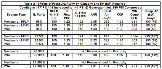
We have learned from Table 2, that by raising the pressure, smaller systems could be utilized to save on capital costs for the nitrogen generator, but the compressor will usually go to the next compressor HP size by going from a 125 PSI to a 150 PSI compressor. In general, the compressed air industry has used a “rule of thumb” of 1% kW increase for every 2 PSI increase, in this case, approximately 12.5%. Over the life of the equipment, approximately 90% of its life costs will be in the energy required to run it. Capital costs, installation and maintenance costs are small compared to the power consumption. That is why it is so important to make wise decisions on your nitrogen equipment selections.
Impact on Temperature Using the Previous Examples and its Energy Impact
Table 3 shows the performance of the same previous examples but adding heat to the compressed air to make the membranes produce more nitrogen per membrane bundle, and coupled with the higher pressure from Table 2, the membrane generator will produce more nitrogen (or require less or smaller membranes to do the job). The circulation heater required for a membrane system is typically 2.4kW per 100 SCFM of compressed air in order to cover a normal range of ambient temperatures in commercially available systems. This can be quite significant on less efficient membrane systems. In the 99.5% example, 104oF, 150 PSI Air which would require approximately a 28 kW heater for the HFLP system. Another Abbreviation, N2 Flow TCF is the temperature correction factor to be multiplied by the initial 100 SCFM flow as well as the pressure correction factor (PCF) to get the increased N2 flows shown in the table.
PSA, on the other hand, loses capacity as temperature rises and its air to nitrogen ratio declines slightly as well. This is a real situation that needs to be looked at in any case, especially in hotter climates and if the PSA is located outdoors. Most quotes from PSA suppliers are at 68oF, because they are more competitive at that temperature. The reality is that at real world ambient, considering the compressor’s aftercooler efficiency, the type of dryer used, the compressed air temperature can easily get to the 104oF used in this example or higher. If higher than 104oF it is recommended to cool the air prior to entry into the adsorber beds.
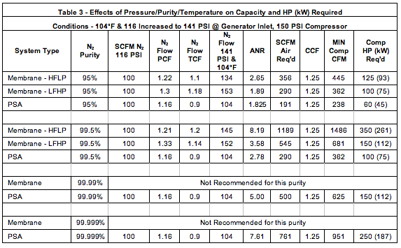
With the addition of pressure and temperature, the compressor sizes go from a low of 60HP to as high as 350HP depending on system and purity selections.
In summary, it is my hope that this article will be most beneficial in providing a little more than a basic understanding of the application of nitrogen generation equipment. This is a very complex industry and much more to understand and talk about, but the purpose of this article was to make consumers aware of the effects of their choices in equipment, and to be able know what questions to ask when selecting the system, membrane or PSA that best meets their needs. There are many other factors other than energy that would affect these choices, but keep in mind, something that was stated earlier. Over the life cycle of the equipment, 90% of the life cycle costs are the energy to run the compressor.
About the Author
Mike Flowe is an industry professional with 31 years of experience in compressed air system application and design, over 20 years of application, design, engineering, consulting and specifying both low and high pressure systems. His experience with control systems, complete system P&ID design, gas booster systems, and previous manufacturing of both membrane and PSA systems, gas boosting equipment, and breathing air gives Mike a broad base of experience to assist clients all over the world with their unique needs. His company, Flowe Nitrogen Systems, is an independent consulting firm that offers a variety of services relating to the compressed air and nitrogen gas, and breathing air industries. The company is located in Orange Beach, Alabama.
For more information contact Mike Flowe, Flow Nitrogen Systems or visit HTTP://FloweNitrogen.com.
To read more Technology articles, please click here.


