
Compressed air is a source of energy in support of manufacturing. It is also a very high cost component in the production of the goods and services at a plant. As such, improving the efficiency of an existing system offers a large savings opportunity. To realize the potential, the system dynamics must be understood and the supply from the compressors must always match the real system demands.
Production processes get their energy from the air stored at higher pressure in the piping distribution system. The air compressors simply replenish the air that is consumed. It is an important distinction to make. The energy input in compressing the air is supplied to the connecting pipes for delivery to the various demands throughout the facility. The energy extracted from the system to perform the required tasks actually comes from air already stored in the pipes. The inefficiencies of a plant air system are affected as much by how the air escapes the system as by how it is generated in the compressor room. Matching the supply with the demand at an optimal level requires that both generation and storage issues be addressed.
Every air system reaches a balance between the air compressor’s supply into the system and the downstream demands that use the air. The energy input from compressing the air equals the energy used plus the system’s inherent inefficiencies. Any more or less energy goes into or is released from storage. Every time there is a change to either side of the equation the system rebalances at a new point. Figure 1 expresses the relationship.
Taking proactive, positive measures to control the balance point ensures the system always operates at its optimum energy level. There are two major sources of energy to draw from to accomplish this.
1. Air stored at an elevated pressure in a fixed volume vessel.
2. Reserve rotating energy of off loaded operating air compressor motors.
Air Storage: Volume alone does not equal storage. In order to replenish or release the energy of the stored air, the fixed volume must realize a change in pressure. Take, for example, a large receiver installed in a compressor room. Unless there is pressure differential between the tank inlet and outlet, no air will flow. It only creates a quiet zone. While adding volume increases the energy level across the entire plant air system, the useable stored energy for controlling the energy balance is zero. To create useable storage requires a change in the receiver pressure. The relationship is expressed as follows:
Vs = Vf x âP/Pa
Where Vs = stored volume (cubic feet)
âP = change in pressure (psi)
Pa = atmospheric pressure (psia)
Vf = fixed volume (cubic feet)
The following example illustrates the importance of the volume/pressure relationship when applying storage properly. Assume the compressors are operating at full capacity and an additional 250 standard cubic feet (scf )of air is needed to satisfy the automated sequencing of the compressor network without disturbing production.
If the system pressure is allowed to degrade 15 psi over the event, the receiver size becomes:
Vf = (Vs x Pa/âP) x 7.481 US gal/cf
Vf = (250 x 14.5/15) x 7.481 = 1,870 gal.
If the system pressure is only allowed to degrade 5 psi, the required receiver would be:
Vf = (250 x 14.5/5)x 7.481 = 5,000 gal.
The 3 steps for applying storage properly are:
- Determine the volume of air that needs to be available to sustain the system during a peak short duration event. For example, a typical system will need 20-30 seconds of supplemental flow in the event a standby compressor must start up and begin contributing air. In the previous example, the 250 scf would represent 30 seconds of flow in a compressor rated for 500 scfm. A simplified approach might be to base the air storage requirement on the largest trim compressor in the network, which is usually the worst case scenario and is often sufficient to cover all other high demand events. Be careful estimating storage using this simplified approach, however, for larger more complex systems, or systems with significant high flow events as the results can lead to improperly sizing the receivers. Engineered storage based upon measured data is usually a worthwhile investment for systems with more than 600hp of operating air compressors.
- Identify the minimum acceptable pressure the system can degrade to without creating a work hazard condition or serious production interruption. The minimum acceptable pressure represents the lowest pressure to which the delivered air can drop, plus some margin of safety to address pressure gradients in the system. Compressors are typically set to operate sufficiently above this level to ensure sufficient quantity of air is stored to be able to ride out the worst case scenario event without causing work interference. The maximum allowable change in storage pressure for a given system while feeding this event, therefore, will be somewhere between the lowest compressor supply pressure and the marginally adjusted minimum acceptable delivered air pressure.
- Size the storage receiver capacity based upon the volume and pressure figures determined in steps 1 & 2. Subtract any existing compressor room receiver capacity from the storage calculation to determine the capacity of an additional receiver(s). Upsize to the nearest stock tank size. Multiple smaller receivers can be used if the new receiver size is physically too large. Receivers can also be installed in a side stream (T’d) arrangement with the main air flow path.
Pressure/Flow Control: The resultant pressure fluctuations from bringing compressors on and off line and the impact of short duration surge demands throughout the plant air system forces the system to continuously seek a rebalance point. The addition of the properly sized air storage receiver mitigates the magnitude and rate of change in system pressure but does not by itself eliminate it. System pressure must still be raised high enough to compensate for the cyclical profile. To stabilize delivered air pressure, the air release out of the receiver must be controlled.
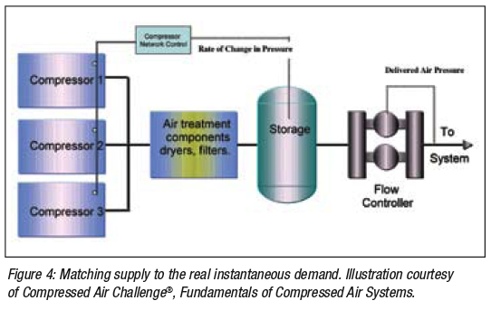
A Pressure/Flow Controller installed downstream of the properly-sized air storage receiver(s) and upstream of the main piping header leaving the compressor room is designed for this task. It senses the pressure at its outlet and modulates the flow control valve(s) accordingly to control the air flow from the receiver to hold the pressure constant. If more air is flowing away than in, the air expands and pressure decreases. The Pressure/Flow Controller opens sufficiently to release air from storage to bring pressure back to the set point. Conversely, if more air is flowing in than out, pressure is increasing and the Pressure/Flow Controller closes to hold air back in the receiver to correct the offset. The Pressure/Flow Controller isolates the supply side from the demand side dynamics and typically stabilizes the delivered air pressure +/- 1psi or less. Figure 2 depicts a typical compressor room arrangement with storage and a Pressure/Flow Controller.
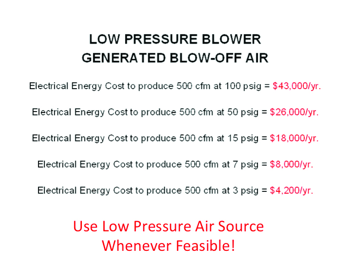
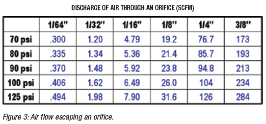
Stabilizing the pressure in the main distribution header eliminates the need to compensate for the fluctuating air pressure by raising the overall system pressure. The delivered air pressure from the Pressure/Flow Controller is set to more closely approach the minimum acceptable. Leaks and unregulated demands in the system consume less air when supplied at the lower pressure. Figure 3 is a table of air flow from an orifice based upon the supply pressure and orifice size. Viewing the use points and leaks as equivalent to an orifice quantifies the savings opportunity.
Reserve Rotating Horsepower: Significant reserve energy is available from air compressor motors that are running but not fully loaded. In combination with the Pressure/Flow Controller and air storage receiver, this reserve energy can be applied in a proactive manner to maintain an optimal balance point. As the receiver pressure changes, the trim compressor loads and unloads accordingly. For systems equipped with a network control system, instrumentation of the change allows a signal to be sent to automatically sequence the operation of the compressors in the network. Figure 4 illustrates the concept.
Running a partially loaded fixed speed compressor is inefficient and can be costly. Storage, therefore, is typically sized to allow unneeded compressors to time out and shut down. Ideally, all operating compressors run at full load with only one compressor trimming at any given time. Substantial air storage must be applied to cover any peaks so a shut down compressor doesn’t have to restart.
The advances in variable speed drive compressors (VSD) offer even greater opportunities to save energy and further enhance the overall performance of a system. Unlike a fixed speed compressor, there is no penalty for operating a VSD compressor partially loaded. Horsepower balances with the demand over the full capacity range of the compressor. A VSD compressor can be oversized to provide additional reserve energy without introducing an added operating cost burden.
The application of a Pressure/Flow Controller with the VSD compressor(s) offers additional savings opportunities and greater stability. Without supplemental storage, a VSD compressor tends to become reactive and ends up constantly chasing the dynamic demands, stressing the compressor motor. The Pressure/Flow Controller eliminates the oscillation and allows the VSD to operate at its maximum efficiency. Additional savings of 7-10% can be realized. Figure 5 depicts the profile of a VSD compressor before and after the installation of the Pressure/Flow Controller.
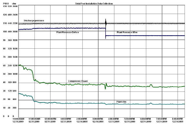
Figure 5: VSD Compressor Installation Pressure Profile
Eliminate waste and the inefficient use of air: With both the supply and demand profile under control, any steps taken to reduce air consumption will positively translate back to the compressors and reduce the input energy. Leak repairs, regulating use points, and the application of high efficiency blow off devices are some cost effective measures to take. It is not uncommon to realize additional savings of 20-30% on top of the savings gained from lowering the delivered pressure and proactively controlling the compressors.


