Abstract
Variable speed control for all types of industrial equipment is now readily available on the market with competitive pricing to non-variable speed controlled alternatives, including in the air compressor industry. With the advent of prescriptive rebate programs for variable speed compressors and other equipment, the demand for these types of controls has increased. General wisdom would recommend a variable speed compressor for all applications, or multiple variable speed compressors within each system. There are significant benefits for systems where the demand changes rapidly to be served by variable speed compressors; by varying the frequency of the input electricity to the motor, a variable speed compressor can speed up and slow down to match supply output to the customer’s demand while maintaining a stable operating pressure within the system. However, many factors should be considered when selecting new air compressors – especially for multiple compressor systems. This paper will provide guidance on the design of variable speed compressors, how they can operate most efficiently with existing compressors, explain the tools necessary to consider when applying variable speed compressors to multiple compressor stations (or any compressors within a system), and provide examples of systems which required improvement as well as systems which were well optimized.
How Variable Speed Compressors Fit Within the Overall System
Variable Speed Compressors
Variable speed control for air compressors is not the panacea for compressed air system efficiency. It can be an important component of an optimized system, provided that it is properly applied. Many factors must be considered before choosing to add even a properly sized variable speed compressor to a system. To understand the part a variable speed compressor would play in creating an efficient system, it is important to take all of the system factors into consideration.
With regard to the variable speed compressor itself, factors to consider include the losses associated with the drive, the increased losses in the motor caused by harmonics in the power supply and the efficient operating range of speeds of the compressor. Drive losses can reduce efficiency 3-5% when compared to a fixed speed compressor. A variable speed drive improves the total energy efficiency only if such additional losses are exceeded by the benefits resulting from the capability to regulate the speed at less than full load conditions. An application where the compressor runs at any steady speed for prolonged periods of time could be made more efficient by using a properly-sized and controlled fixed speed compressor (or compressors) that does not have the losses mentioned above.
Fixed Speed Compressors
Fixed speed compressors are typically switched between load (the compressor is running and producing full flow), idle (the compressor is running but is not producing air) and stand-by (the compressor is off but ready to restart). Idle operation is necessary when the required switching frequency between full flow and zero flow exceeds the maximum permissible starting frequency of the motor.
Power consumption during idle is typically 15-35% of full load power consumption. However, for lubricated screw compressors, this low power level is reached only after the pressure in the separator has been relieved. This can take 30-60 seconds. In poorly designed systems, it is not at all unusual for compressors to switch from load to idle every 20 seconds. This can result in an average power consumption of 90%+ to supply a demand of ~50%.
Overall System Design
Designing a proper and efficient compressed air system requires knowledge of the strengths and weaknesses of each compressor type and how they should be applied. Because compressed air is an essential part of the
manufacturing process and therefore an indispensable part of the infrastructure like electricity, interruption of compressed air supply can cause an interruption of production and also possible consequential damage. Reliability and availability of compressed air supply should be ensured by a certain redundancy to compensate for planned maintenance or breakdown. Generally this means that the number of compressors, the individual compressor sizes and the total combined flow of all compressors have to be chosen in such a way that an uninterrupted compressed air supply is ensured, even if the largest compressor is shut down for maintenance or if it fails. This philosophy can be extended to dryers and filters to ensure complete system redundancy.
For example, in a compressed air station with only two compressors, the smaller one would have to be sized to provide enough flow to meet the peak demand or that in a compressed air station with three compressors, the two smallest would have to be sized to provide enough flow for the peak demand. This example shows that realizing redundancy in compressed air stations with only two or three compressors is associated with large additional investment, as this typically increases the overall horsepower of the station. These circumstances in addition to possible improvements regarding controllability typically lead to the installation of several compressors in industrial compressed air stations.
In addition to the multiple compressor considerations weighing the costs and the benefits from including one or more variable frequency drive compressors should be analysed. The costs would include capital as well as potential increased maintenance cost over the lifetime of the equipment, plus the increased complexity of the compressor requires advanced training in maintenance and operation.
It is well known that in multiple compressor installations the energy efficiency is significantly improved by the use of a master control which coordinates the operation of the individual compressors. The most important aspect of “coordination” in this context is to control the operational modes and the transition between these modes appropriately (e.g. load, idle, stand-by for fixed speed compressors, operating speed of variable speed compressors, shut down or start-up for all types of compressors).
The master control decouples the individual compressors from the system demand pattern by “translating” the actual values and the trend of the total demand along with the storage pressure, the actual and previous operating conditions, and the availability of the compressors, to an efficient control scheme for all compressors minimizing the total energy consumption.
In particular the control scheme applied should benefit from the individual advantages and avoid the individual disadvantages of the compressors in the system. These include:
- Supply short-term demand fluctuations using the control capability of variable speed compressors, but avoid long-term operation in less efficient operating points and frequent shut down or start-up
- Use the high full load efficiency of fixed speed compressors, but avoid long-term idle operation and frequent switching between operational modes
Installations with several fixed speed compressors combined with one or two variable speed compressors are very energy efficient over a large range of flows, if a master control is applied. The master controller will allow the variable speed compressor(s) to supply the short and medium-term fluctuation of the total demand to eliminate the need for frequently switching fixed speed compressors. The master controller will also operate the fixed speed compressors in such a way that the actual base-load demand is supplied by an adequate and efficient combination of compressors in load and in stand-by. In such installations with two variable speed compressors and one or more fixed speed compressors, the additional losses of the variable speed compressors should be exceeded by the efficiency gain of the entire system as the system rarely sees frequent switching and/or idling of fixed speed compressors. An overall cost analysis can be completed to determine the return on investment by adding a variable speed compressor(s) to the system as opposed to other alternative solutions.
System Sizing and Compressor Selection
Measuring the System Demand
Given the assumption that a variable speed compressor will be one of several compressors required to meet the total demand, the first thing required for properly applying a variable speed compressor, or any fixed speed compressor for that matter, is a demand profile. A demand profile is best if measured using a flow meter installed downstream of air treatment equipment and downstream of dry storage. This way the profile reflects the actual system demand and is not a supply profile. Measuring compressor response to system demand, a supply profile, will produce an approximation of the demand, but storage becomes a demand in that case and must be considered. Without a profile, it is very difficult to properly size the variable speed compressor that can cover the variations in demand in an efficient manner. This demand profile should accompany individual compressor operational signals, along with power consumption, and multiple system pressures. These signals together will provide an overall baseline of whether the supply is able to meet the demand.
Understanding the System Operation
An example of a possible, and simplified, flow profile is shown in Figure 1 below. The overall flow percentage is graphed against time in seconds.
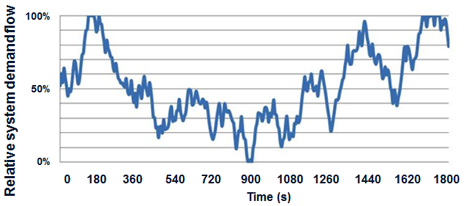
Figure 1: Sample demand flow profile.
Figure 2 below shows how a master controller should operate individual compressors (in this example two fixed speed compressors and one variable speed compressor) to match the system demand illustrated in Figure 1 with minimum pressure fluctuations.
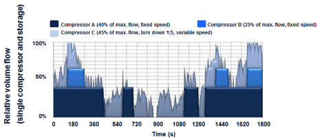
Figure 2: Multiple compressor system operated by a master controller.
The compressors have been sized for the application so that the base-loaded, fixed speed compressors have a capacity that fits within the control range of the variable speed compressor. This allows the fixed speed compressors to be started and stopped when significant changes in demand occur while the variable speed compressor adjusts for variations in demand that are within its control range. Frequent switching between load and idle on the fixed speed compressors is eliminated. The fixed speed machines are either at full load or stand-by (offline entirely).
Compressor Selection
In the example above, the compressor sizing includes two smaller fixed speed compressors and one larger variable speed compressor. When base-load compressors are sized within the control range of the variable speed compressor, this ensures the ability of the station to maintain a stable plant pressure and maintain the highest efficiency possible throughout the prevailing demand profile.
The control range of the variable speed compressor is defined as the difference between maximum output flow of the compressor at rated pressure and the minimum flow of the compressor at rated pressure. When the base-load compressors are sized within this range, and the compressed air station includes a master controller, then the compressed air station can maintain a stable operating pressure at various flow levels. In the example, there are two different horsepower base-load compressors. This can allow the variable frequency drive compressor to operate within its maximum efficiency range at varying flow levels. Figure 3 highlights the general efficiency of a 350 hp variable speed compressor by graphing the percentage of full load flow against the compressor's specific power (kW / 100 cfm-fad). Note that the most efficient points are typically between 40% and 85% of full load which is supported by the data in Figure 3. These efficiency gains using a single variable speed drive compressor can be expanded to a multiple compressor station as a whole through advanced compressor controls.
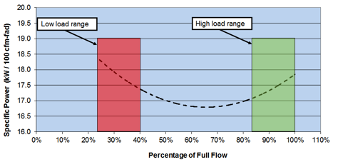
Figure 3: Sample efficiency of variable speed compressor.
Advanced Compressor Controls: The Master Controller
The key to effectively addressing changes in demand within a multiple compressor system is the correct type of master controller. The master controller should not simply generate multiple pressure bands and control each compressor within its assigned band. The controller must be able to maintain the most effective pressure band and control all compressors within that band. It must monitor the rate of change of the pressure to determine the change in flow demand and calculate the appropriate and most efficient response to that change. It must be able to monitor the starting frequency of all compressors in the system so that they can be quickly or immediately switched to stand-by and avoid any idle mode running. However, even with a sophisticated master controller, if the compressor selection is not appropriately made from the beginning, then the efficiency potential of the system can suffer.
Figure 4 illustrates how the master controller translates changes in system pressure into a suitable control scheme for the compressors using the same example in Figure 1 and 2. Note that none of the compressors are following the system demand. The controller separates their controls from the demand and determines how they should run to maintain a stable pressure and above the minimum required pressure.
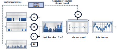
Figure 4: Characteristics of a compressed air system master controller.
By using the correct combination of master control and properly sized compressors, concerns about part-load efficiency of the fixed speed compressors is eliminated. They will not run any significant time in idle mode, running instead in full load or stand-by. It should also be noted that a back-up compressor in the system example would need to have a flow rate as great as, or greater, than the largest machine in the system. In an actual application, this flow profile would likely have resulted in more than just three compressors being specified. Breaking the demand into smaller units could reduce the size of individual compressors and allow for smaller back-up or back-up covered by multiple machines.
Selection by Analysis Revisited
It is critical to revisit the compressor selection. By designing the compressed air station based on measured data, the system is in a better position to be optimized at demands within the production than without measured data. In many cases, compressors are added as production equipment is added to the facility. In these cases, common wisdom suggests that simply adding a variable speed compressor on top of existing fixed speed compressors can provide significant energy savings. However, this typically does not address key areas of operation as it does not include a full understanding of the overall system dynamics. In these cases it is always recommended to complete a comprehensive air demand analysis, or air assessment, to understand the compressed air dynamics.
What Is Control Gap?
Control Gap Explained
Often times the variable speed compressor selected is the same size as a base-load compressor or smaller. When designing a compressed air system, if the control range of the variable speed compressor is not considered, this can result in one or more compressors operating in an inefficient manner, such as cycling between load and idle of a fixed speed compressor or significant ramping up and down of the variable frequency drive – or both at the same time. When these types of events occur, the plant often refers to the compressed air system as “out of control,” and an unusual pressure fluctuation in the facility persists which can affect production. This is commonly referred to as a “control gap.”
The control range of the variable speed compressor is critical to avoiding a control gap. When one or more fixed speed compressor is sized within the variable speed compressor’s control range, the control gap can be avoided. Figure 5 shows an example system with 150 hp variable speed drive compressor and multiple 100 hp fixed speed compressors. The maximum flow of the 150 hp variable speed compressor is 735 cfm-fad at 110 psig and the minimum speed is 150 cfm-fad, therefore the control range of the variable speed compressor is 585 cfm-fad at 110 psig. The two fixed speed compressors are both rated for 497 cfm-fad at 110 psig and therefore fit within the control range of the variable speed compressor. As can be seen in Figure 5, the system can provide a steady operating pressure throughout the flow range of the system as long as the system is properly controlled with a master controller.
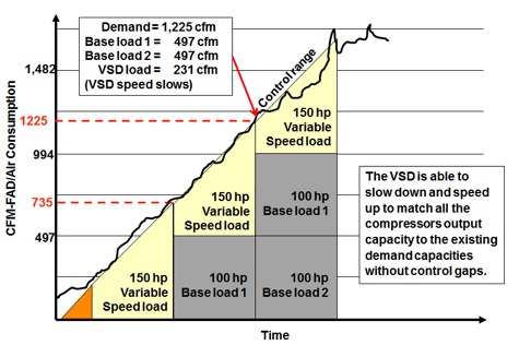
Figure 5: System selection to avoid control gap.
Control Gap Example 1: Same Sized VFD and Fixed Speed Compressors
Figure 6 shows a system which exhibits a control gap between the variable speed compressor and one base-load compressor. In this system there was one fixed speed 350 hp compressor, one variable speed 350 hp compressor, and one 200 hp fixed speed compressor. This system did not have a master controller for all the compressors. Figure 6 highlights a period where the medium load unit (200 hp fixed speed compressor) was operating fully loaded. This consequently resulted in multiple periods where the variable speed compressor and the same sized base-load compressor were cycling between load and unload together producing a fluctuating pressure of 8 psi and an uncharacteristically high specific power (kW / 100 cfm) for the facility.
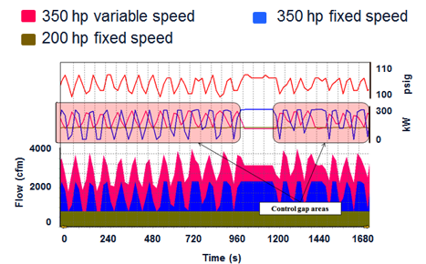
Figure 6: Control gap example 1 highlight.
Master Controller Benefits
With a properly selected master controller for all compressors available, the 200 hp fixed speed compressor would only load during lower production periods and the 350 hp variable speed compressor would trim. The master controller would transition the 200 hp fixed speed compressor off when higher production periods occurred, allowing the 350 hp fixed speed compressor to run at full load and the 350 hp variable speed compressor to trim. This would operate the station more efficiently at each possible production level.
Control Gap Example 2: Same Sized VFD and Fixed Speed Compressor
Typically, with a same sized variable speed compressor and base-load compressor, the variable speed compressor is operated as the first-on compressor. This usually ensures the facility will have the best potential energy efficiency during off-production periods. However, during peak production without a master controller, and the compressors operating in a cascade control, the variable speed compressor can run fully loaded with the base-load compressor trimming resulting in higher than normal specific power. This can actually increase operating costs, and will result in a fluctuating plant pressure. Figure 7 shows a 150 hp fixed speed compressor operating as the trim compressor, and the 150 hp variable speed compressor operating 100% of full load.
Since the variable speed compressor control range is smaller than the fixed speed compressor there is an inherent control gap within the station. The variable speed compressor could operate as the trim load unit during peak demands with the installation of a master controller; however, the benefits of the variable speed at lower demands may not be realized. With the variable speed compressor as the base-load and the fixed speed compressor as the trim-load compressor, the facility is spending 20% more in energy than a system with one 150 hp variable speed compressor, one 75 hp fixed speed compressor, one 150 hp fixed speed compressor, and a master controller. The master controller would properly select all existing units to match supply to demand while maintaining a stable operating pressure rather than a fluctuating system pressure, and the 75 hp fixed speed compressor would fit within the control range of the 150 hp variable speed compressor thereby avoiding the control gap.
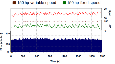
Figure 7: Control gap example 2 sample operation.
Control Gap Example 3: Larger Fixed Speed Compressor with Smaller VFD Compressor
With a smaller sized variable speed compressor and a larger base-load compressor typically the variable speed compressor is operated again as the first-on compressor. This operation ensures that the facility will have the best potential energy efficiency during off-production periods, as long as the variable speed compressor is large enough to meet demand alone. However, during peak production, when the demand is higher than the supply of the variable speed compressor, the base-load compressor will be needed. This often results in more than one compressor loading and unloading almost simultaneously, and the compressors fighting each other for control of the station; again increasing the specific power and increasing the overall cost of operation of the plant.
Figure 8 shows a system with two 125 hp fixed speed compressors, one 100 hp variable speed drive compressor and highlights a period where the control gap between the variable speed compressor and the fixed speed compressors is evident. In this case, one 125 hp fixed speed compressor is fully loaded, which is a good practice. The demand increases slightly and therefore the 100 hp variable frequency compressor loads to trim. However, since the variable speed compressor was not large enough to handle the entire increase in demand, the second 125 hp fixed speed compressor was subsequently loaded. The additional supply flow from both the 100 hp and the 125 hp compressors was too much for the demand and both compressors subsequently unloaded. The process continued and the specific power of the station became less efficient, as well as the increased wear on the units from constant cycling.
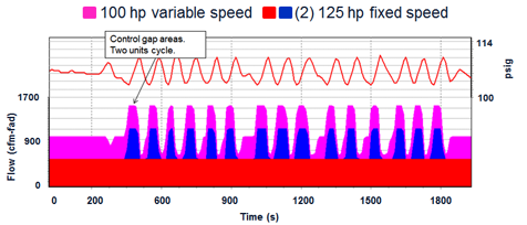
Figure 8: Control gap example 3 highlight.
In this particular scenario, adding a 75 hp fixed speed compressor along with a master controller to the existing fixed speed compressors and variable speed compressor would avoid the control gap and balance the system by maximizing part load power efficiency of the station.
Avoiding Control Gap
Properly Sized Equipment
Figure 9 shows a system sized based on a demand profile to avoid any control gaps within the demand. The system included a 75 hp variable frequency drive compressor, a 40 hp fixed speed compressor (medium load unit), and a 75 hp fixed speed compressor (base-load unit) with a master controller. The master controller properly selected between the two differently sized fixed speed compressors to operate fully loaded while the variable frequency drive compressor trimmed.
The addition of the medium load unit avoided the inherent control gap between the two 75 hp compressors. Along with the master controller, the station provided a relatively stable operating pressure throughout the various demand levels while maintaining an efficient specific power throughout this sample day of operation. Figure 10 highlights the consistent specific power over an entire sample day regardless of the demand profile. The only mild increase in specific power occurred during a transition to a lower supply range which represents a relatively small percentage of operation.
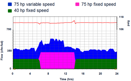
Figure 9: Properly designed system with master controller.
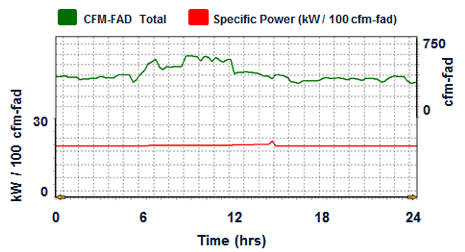
Figure 10: Flow and efficiency for properly designed system.
This type of operation results in a low specific power, a low overall energy cost due to the compressors spending little time cycling between load and unload, as well as little time idling. Table 1 shows a one month sample for the system discussed. All three units have a duty cycle close to 100%, meaning that the idle costs are less than 1% of the overall energy consumption. The added benefit will be lower maintenance costs to the cycling components of the individual compressors as well as stable plant pressure. Adding a third 75 hp fixed speed or variable speed compressor would provide complete redundancy to this station and would be highly recommended.
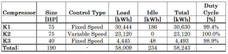
Table 1: Sample monthly energy consumption and duty cycles for properly designed system.
Summary and Conclusions
In all of the examples shown, the systems which were sized properly based on a demand profile, and operating on a master controller provided the lowest energy consumption and most efficient station operation regardless of the demand. The systems which were either not sized based on a demand profile, did not include a master controller, or were not sized appropriately resulted in a higher than expected energy consumption, higher overall maintenance costs, and the appearance of less stable operating conditions by plant personnel.
Key Points:
- In typical industrial applications, several compressors supply the total flow.
- Multiple compressor systems should be controlled by a master controller to operate in different combinations and operating points or operational modes.
- In such installations, an individual compressor follows the control scheme of the master controller and does not independently respond to or reflect changes in systems demand.
- The combined operation of fixed speed and variable speed compressors allows the controller to use the individual advantages of each type of compressor to its full extent and avoid the disadvantages to achieve high system efficiency by decoupling the compressors from the actual demand.
- The proper design of a compressed air system and the choice of compressors cannot be done without first determining the demand profile.
- The design may include multiple variable speed compressors, one variable speed compressor or none at all depending on the prevailing demand profile and other mitigating factors such as capital cost, return on investment, and application.
|
AUTHOR’S BIOGRAPHY Neil Mehltretter has a Bachelor’s Degree in Chemical Engineering from The University of Florida. Neil first worked on energy efficiency projects during his time at The University of Florida, and after graduation, he worked in the alternative energy industry before joining Kaeser Compressors, Inc. in 2004. Neil is a Master Certified System Specialist through Kaeser’s Factory Training Program and has completed the Compressed Air Challenge Level 1 and 2 training courses. Neil is also a Qualified AIRMaster+ Specialist. During his time with Kaeser, he has supported numerous compressed air projects and air audits as well as served as the primary contact for the installation of Kaeser’s master controller, the Sigma Air Manager. Currently Neil manages the design and engineering services for Kaeser, which includes energy improvements as well as compressed air selection. Email Neil Mehltretter |
To read more Air Compressor Technology articles, visit www.airbestpractices.com/technology/air-compressors.


