Good morning. Why are Vapor Recovery Units important to managing Greenhouse Gas (GHG) emissions?
Good morning. Vapor Recovery Units prevent oil and natural gas upstream processes from emitting greenhouse gases. Underground crude oil, for example, contains some composition of gas vapors when it is brought to the surface and stored in a storage vessel. The largest component of these vapors is methane (between 40-60%). Other vapors can include propane, butane, ethane, nitrogen, and carbon dioxide – to name a few. Methane, of course, is a greenhouse gas that remains in the atmosphere for approximately 9-15 years and is over 20 times more effective in trapping heat in the atmosphere than carbon dioxide (CO2).
In the past, “gas flaring” was a common process at well sites. These surplus, combustible vapors were seen as a “waste gas” or as a safety issue. The solution was to burn-off these vapors into the atmosphere. We can remember a time, here in the Airdrie, Alberta region, that there were so many flares that at night they looked like street lights!
Are there regulations covering “gas flaring” now in Canada?
Yes, there is now a strictly enforced regulatory environment for all “gas flaring”. Canada now views gas flaring as a significant environmental problem, contributing significantly to global emissions. All oil and gas wells must comply with specific vapor recovery directives issued by the ERCB (Energy Resources Conservation Board).
The ERCB is a quasi-judicial agency of the Government of Alberta. They issue directives and do inspections and monitor drilling operations. At first, oil and gas operators had to pay a fine for emitting any GHG’s. Now, the ERCB will shut down a facility if vapor recovery processes are not adhered to and any GHG’s are emitted.
What types of packages do you build for Vapor Recovery Units?
We build “small” and “large” packages. The small applications are designed to recovery the vapors present at the top of the oil storage tank (s) at the drill site. These smaller packages use a five (5) horsepower blower installed on top of a receiver tank. We run a line from the top of the oil storage tank over to our receiver tank. Our package includes a temperature switch and a differential pressure switch (from intake to discharge) on the blower.
As pressure builds up in the holding tanks for the oil, we will start up the blower to draw out the gas vapors. The blower will then push the gas into some process where they can re-use it or it will be sent to a natural gas compressor or engine. The suction pressure is in the range of a few ounces and the discharge pressure is between 5-8 psig. A transmitter is reading suction pressure on the unit.
The air receiver acts as a separator and has its’ own liquid level gauge. Liquids settle out in the tank and the blower takes the gas off the top of the tank. We will take suction pressure from a positive few ounces, to 5-8 psig to send it to process. Our transmitter is reading suction pressure.
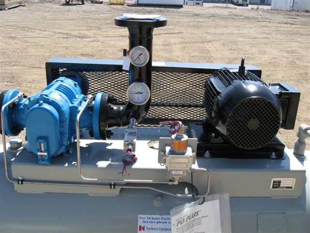
Vapor Recovery Unit with a 5 hp Blower
What kind of blowers do you use and what does the total package look like?
We normally use the Tuthill PD Plus Series Blower. They are double-envelope blower designed for gas. The double-envelope feature ensures a tight gas seal. This ensures ZERO gas leaks. You have to remember that many of these packages go inside a building. We actually build many structures/buildings for these packages. Leaks cannot be tolerated.
We have standardized on double-envelope blowers for all installations involving vapor recovery. We are aware of some people selling single-envelope blowers for outdoor installations. We don’t recommend this as there can be leaks.
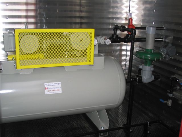
Vapor Recovery Units can be enclosed in their own building.
Please describe the larger packages.
When higher pressures are required, the vapor recovery units get larger in size. Higher pressures can be required because the gas has to be pushed a further distance or because it’s being pushed into a higher-pressure line.
Pictured here is a two-stage package built to achieve pressures exceeding 40 psi. The system is installed in a natural gas process plant designed to strip out unwanted gases. Multiple natural gas wells pipe in to this centralized process plant. The application is to recover CO2 and H2S gas (hydrogen sulfide or sour gas) from natural gas. Hydrogen sulfide (H2S) is a deadly gas - only 1 ppm from a H2S leak can kill a man. They like to find it though, because they strip H2S off to form sulfur for agricultural purposes. There is a lot of it here in Western Canada.
This two-stage unit has a 200 horsepower blower for the first stage. The second stage uses a 150 horsepower blower. Both blowers use Tuthill double-envelope, gas-type, lobe technology. Both blowers are controlled by individual variable frequency drives. We chose individual VFD’s because we are drawing off a process inlet flow which varies greatly depending upon how much natural gas is there. We can’t overdraw on their lines, so we control the speeds of the two blowers to match the interstage pressures (to maintain the pressure). We control the speeds of each blower to match or maintain intake, interstage, and outlet pressures and ratios. Energy savings can also be achieved vs. some single-stage units which have to use recirculated gas to maintain interstage pressures. In this manner, we were able to match input power requirements and eliminate recirculation gas.
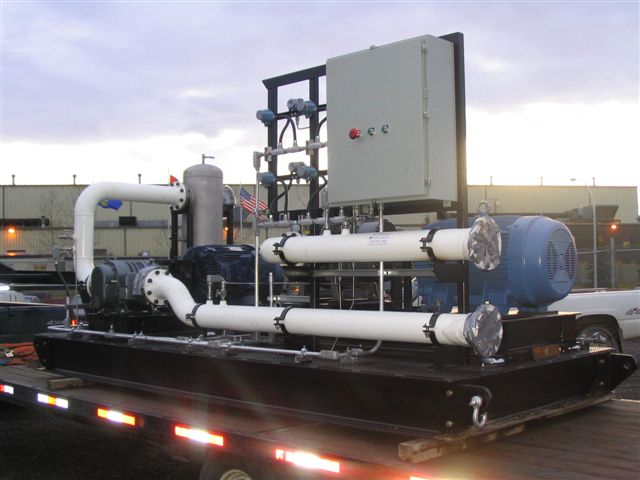
A two-stage blower package delivers 40 psig pressure
Do you have to manage the condensate as well?
Yes. Natural gas is saturated or “wet”. They want to collect these condensates because they contain valuable gases as well. We gather these liquids, after the first stage, in a mechanical separator vessel. There is a cooler to condense the liquids, the separator draws out the condensates, the dry gas goes into the second-stage blower, and then it’s off to the process.
Do you ever reach pressures requiring a compressor?
Yes. We have seen small-flow applications at higher pressures in the 60-100 psig range. The have been applications with natural gas requiring higher pressures due to long distances the gas has to travel and due to pressure losses in the pipes.
In these cases, the unit will take elevated suction pressures of up to 5 psig and go to a 60-100 psig discharge pressure. Some well pressures do reach 5 psig. The gas compressors are specially formulated to handle the rigors of gas and a 2-3% H2S content. All yellow metals are removed from the compressor internals. The gas intake assembly is configured to have a threaded inlet (for pipe intake), the intake cover assembly ensures a sealed unit, and oversized oil-cooler and after-coolers with CRN registrations are specified. The unit also has a remote oil filter system and uses special oils (with better emulsification) which won’t get chewed up by the H2S.
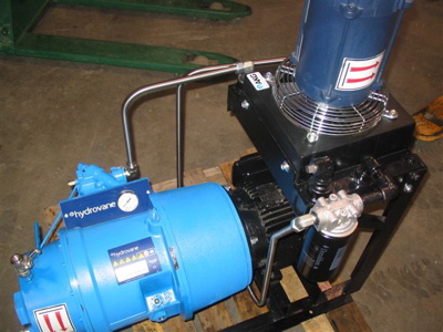
Gas compressor package for 60-100 psig pressure
Do instrument gas systems need vapor recovery packages too?
Yes. We have designed instrument gas systems for many years for customers who didn’t have compressed air on-site to run their valve and actuator instruments. Instead they used the natural gas they had on site and would flare off any excess gas. With the new regulations and inspections, we have seen a large increase in demand for Vapor Recovery Unit packages at these sites. These customers now have to install an Instrument Air package and a Vapor Recovery Unit to deal with these vapors. In general, this market is decommissioning the use of instrument gas and putting in instrument air packages. This is just getting started due to GHG emissions as they are going for zero percent gas flaring in the whole process.
Are there any other new applications for Vapor Recovery Units?
Absolutely. Our region is famous for the “tar sands” (also known as the oil sands). A process used to extract oil here is called Steam Assisted Gravity Drainage (SAGD). Steam is injected into the upper wellbores to heat the reservoir. As a result, bitumen drains into lower wellbores and is brought to the surface.
The oil sands industry, using SAGD processes, are now designing new systems where the water is boiled off and turned into steam. It is then sent into evaporators, recondensing water out and separating the other gases. We are involved with supplying 20 horsepower blowers to take steam at a low pressure and draw it through a inlet scrubber. We then push it downstream into a gas separation process. This process delivers zero percent gas venting – and the ducks are safe!
Thank you for your insights.
For more information, please contact Sid Van der Meer, Northwest Equipment, tel: 403-945-1988, email: [email protected], www.nwequipltd.com


