
“Compressed air systems with multiple compressors operating to supply demand requirements present unique challenges in compressed air system control schemes.” states “Best Practices for Compressed Air Systems”, in an introductory statement dealing with multiple compressor controls. An original, and still common, method of control in multi-compressor systems is to use a cascaded arrangement of set points as shown in Figure 1. This control strategy was discussed in our article in the November, 2010 issue of Compressed Air Best Practices Magazine. This is the simplest and least expensive method of compressor control, but it suffers from a number of disadvantages:
- Average compressor discharge pressure is always higher than required,
- It is difficult to accommodate multiple compressor sizes,
- Adequate control is often subject to manual adjustment of pressure switches or manually operating compressors on a time schedule.
- It is difficult to keep the most efficient compressor in trim duty
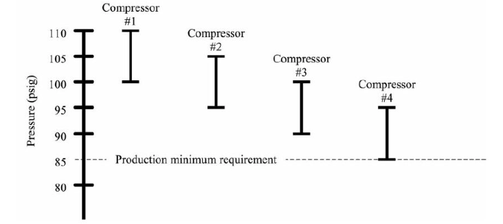
Figure 1- Cascade control should not be used with VSD compressors.
This cascaded arrangement assumes each compressor has the same characteristics when running at partial load, very often not the case, especially if one of the compressors is a variable speed drive (VSD) controlled unit.
The most efficient way to run a multi-compressor system is to hold any required fixed speed compressors at either fully loaded or off. The compressor with the most efficient part-load characteristics should run as the trim unit. A trim unit is the one designated to supply part load operation, where the combination of required compressors at any given load requires a fraction of one compressor. A VSD compressor, which by design has good part load energy performance, normally becomes the designated trim compressor.
The selection of the size of this trim compressor and its pressure settings become important when implementing this type of control. If incorrect choices are made there will be “control gap” issues that will cause the system to become unstable, with possibly two or more compressors inefficiently “fighting” for trim position.
Control Gap
If a trim compressor is to be set to always supply partial load, it must have its pressure settings coordinated so a large enough pressure control band is inside, or within, the pressure band of the base compressor as shown in Figure 2. If set in this arrangement, the VSD compressor will control system pressure if it is supplying partial load. If system loading increases to a level exceeding its capacity, the compressor discharge pressure will be reduced to the load (start) setting of the base compressor. The base compressor will then start producing air at full load capacity, pushing the discharge pressure back up to within the control band of the trim compressor. If the load remains above the total capacity of the base compressor, the trim compressor will supply the remainder of the partial load that is above the base compressor capacity.
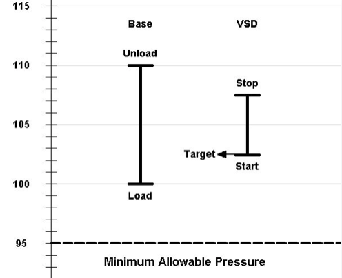
Figure 2- The VSD compressor setpoints withinthe base control range.
If the load falls to less than the capacity of the base compressor, the trim compressor will try to maintain pressure by reducing its capacity to zero, but even with this capacity reduction the capacity of the base compressor will force discharge pressure up to the point where it will unload and time off. Once this base capacity is removed from the system, the discharge pressure will fall back down to within the trim compressor’s control range, where it will take control again.
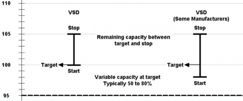
VSD Compressor Control RangeVSD compressors are designed to control discharge pressure within a very accurate range while within the compressor’s variable speed range. However, VSD compressors can only slow down so much, with the minimum speed point often depending on the characteristics of the compressor. Below the minimum speed point, the compressor acts like a load/unload (or start/stop) controlled compressor with the compressor operating between two set pressure settings. Figure 3 shows a typical compressor control range. Note some compressor manufacturers fix the target pressure at the bottom of the control range, where others allow the target pressure setting to be adjustable to any point within the load/unload range.
Figure 3 – VSD Control Ranges. |
Sizing Matters
This efficient control method depends on the correct sizing of the variable trim capacity. Consider an example system where a 75 HP trim compressor with a capacity of 300 cfm and a 100 HP base compressor of 400 cfm capacity are programmed to work together with the arrangement just discussed. Everything works fine if the system loading is between zero and 300 cfm, or between 400 and 700 cfm. But if the loading settles to within 300 and 400 cfm problems occur. This is because a size mismatch creates a 100 cfm wide “control gap” in which neither base nor trim compressor can efficiently supply the load. This control gap is located within the system capacity control scheme at a point representing the difference in the sizes of the compressors and occurs when the trim capacity is less than the base capacity.
In our example system, if loading reaches, say 350 cfm, the trim compressor discharge pressure will fall to the point where the base compressor will start and begin producing air. It will push the pressure up past the control range of the trim compressor where the trim compressor will unload (or stop), however, this removes only 300 cfm, and the base compressor is 400 cfm, so there will still be an excess capacity of 50 cfm, driving the pressure up to the unload point of the base compressor. When the base compressor unloads the pressure will fall to within the control range of the trim compressor, and it will start, but because it has only 300 cfm capacity, and the actual load is 350 cfm, the pressure will continue to fall to the load point of the base compressor. If the load remains stable within the control gap the two compressors will continue to “fight” for trim position, with significantly reduced system efficiency.
One solution to this problem may be to provide a trim compressor that is equal to, or larger, than the base compressor. The duration of the control gap operation is often dependent on the continuous or intermittent system demands. In some instances, the problems associated with the control gap can be reduced by increased storage capacity alone, or in combination with a pressure/flow controller for fixed speed compressors. The Compressed Air Challenge (CAC) recommends a minimum of three (3) gallons of storage capacity for the trim compressor. In this case approximately 1,000 to 1,200 gallons is recommended.
Correct Sizing Example
Consider an alternative system with a VSD compressor of 400 cfm capacity and the base compressor of 300 cfm. If the system loading reached 350 cfm the VSD compressor would have more than enough capacity to handle this load. If the system loading increased to say 450 cfm, the system pressure would fall to the load point of the base compressor, as described previously, and the base compressor would load and start to supply 300 cfm. The remaining 150 cfm would then be supplied by the VSD compressor, which would automatically adjust speed to maintain target pressure within its variable range. The system loading would need to fall lower than 300 cfm before the base compressor would force the pressure up so it would unload, passing the full system demand back to the VSD compressor. Because the VSD compressor is larger than the base compressor by 100 cfm, there is a 100 cfm wide overlap band. System loading must increase above 400 cfm to start a base compressor, but must decrease to below 300 cfm to cause the base to unload. This “debounces” system control and prevents the compressors from constantly sequencing for control if the system loading is just skirting the edge of the capacity ranges of the two compressors.
Pressure Control Band Overlap
If the VSD compressor variable capacity range (cfm) is larger than the base compressor’s full capacity rating (cfm), the pressure band of the VSD compressor need not be fully inside the load/unload pressure band of the base compressors for efficient operation (Figure 4).
In the previous example, if the 400 cfm compressor had a turn down of 80%, or 320 cfm, this variable capacity range still exceeds the 300 cfm capacity of the base compressor and still provides 20 cfm of overlap capacity. In this case the VSD compressor need not fully unload and turn off during transition between loads requiring the base compressor; it only needs to run at minimum speed. This reduces the need for the VSD to turn off and blow down (if applicable), allowing the unit to start producing air faster when called upon. It will therefore enable a narrower pressure band control between the VSD target pressure and the base compressor load point, reduce the average discharge pressure and save energy.
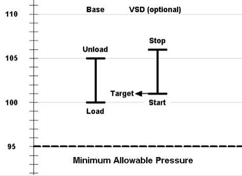
Figure 4- Alternate control range setting if VSD variable range is larger than the base.
For more information visit the Compressed Air Challenge® website or contact Ron Marshall, Marshall Compressed Air Consulting, tel: 204-806-2085, email: [email protected].
To read more Compresor Controls articles, visit www.airbestpractices.com/technology/compressor-controls.


