Introduction
Recently, this major pulp & paper mill made compressed air optimization a mill-wide priority. At the request of the utility company providing energy to the mill, Compression Energy Services performed a comprehensive energy analysis that outlined the following four energy efficiency measures (EEM’s) for the mill to consider.
EEM #1: A comprehensive compressed air management system that runs the optimal compressors in the optimal mode.
EEM #2: Upgrading the compressors to run more efficiently, particularly at lower pressures.
EEM #3: Replacing the dryers to eliminate purge and allow pressure reduction.
EEM #4: Replacing many of the large dead-load uses of compressed air with alternate technologies.
There are four “energy efficiency measures” (EEM’s) that this report recommends. However, since the cost risk and implementation difficulty is highest for measure 3, with the least energy savings and highest EEM payback, we are providing two project packages. The lower cost, lower risk package is EEM 1, 2, and 4 and can provide energy savings of 4.5 million kWh/yr and \$206,808 per year with a ROI of one year. Due to article length limitations, this document will share only the findings of the EEM 1,2, and 4 project package.
Baseline Compressed Air Equipment
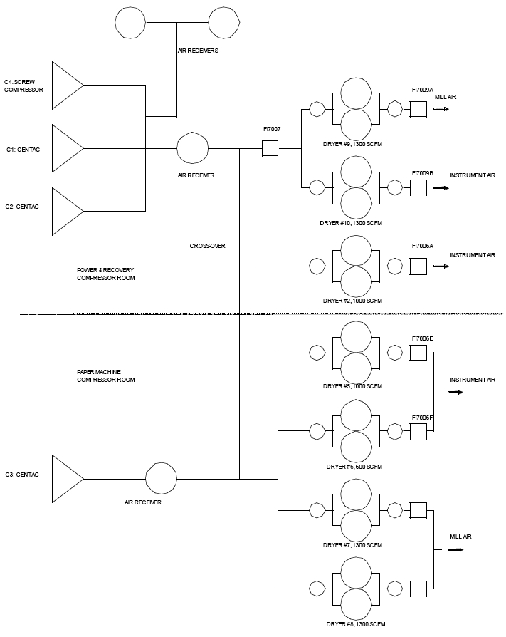
The compressed air equipment is located in the Power & Recovery Compressor Room and in the Paper Machine Compressor Room. The equipment detail is listed below. At the end of the article we have provided a box diagram of the equipment in the system.
Power & Recovery Compressor Room:
(2) 700 HP Centac Centrifugals (approx. 2,636 acfm full-load capacity)
(1) 300 HP Screw compressor (approx. 1488 acfm full load capacity)
(2) 1300 scfm heatless dryers
(1) 1000 scfm blower purge dryer approx. 6000 gal storage, (3) 2000 gal.
Paper Machine compressor room:
(1) 700 hp Centac Centrifugal (approx. 2,748 acfm full-load capacity)
(1) 1000 scfm heatless dryer
(1) 600 scfm heatless dryer
(2) 1300 scfm heatless dryers (approx. 2000 gal storage)
Controls Baseline
Typical operation over the baseline period includes a variety of partly manual and automatic control modes, which result in four compressors running rather than three (which is a rough measure of optimal control) about 52% of the time. This was determined from long-term main motor current trend data from Customer.
The sub-optimal condition of four compressors running occurs because of the lack of an integrated management system. They have enough automation to get the standby compressor to automatically start if pressure drops to a critical point, if the average pressure is below 80 psig for more than 5 minutes or under 70 psig instantaneously. However, the standby compressor does not automatically stop once the event that caused it to start has passed. There is no control system in place that can determine when a compressor should be unloaded and safely shut off, so that it won’t immediately need to be restarted. The average compressor discharge pressure is about 97 psig.
System Integration Baseline
The baseline piping system is cross-connected on the wet side, between two compressor rooms, one in the Power and Recovery (P&R) side of the mill, and the other below the paper machines (PM). These two compressor rooms produce all of the dryer air needed for the Instrument Air (IA) and Pulp and Paper Mill Air (MA) systems, which comprise the entire compressed air system for the mill. These two subsystems are presently segregated, even though they are essentially at about the same pressure (85 psig) and dew point (-40 deg F). The IA system as a whole is connected by a 3” header that runs through the mill. However, the line size is not adequate to allow the IA system to be fed from either the P&R or PM compressor room. The MA appears that it might have an adequate header size to be fed from either side. Thus, the PM compressor, Centac 3, can never be shut down without rental compressors being brought in, which is very expensive.
Compressed Air Usage Baseline
The baseline constant usages of compressed air that are not related to variances in production are referred to as “dead loads” in this report. Dead loads include many continuous blowing compressed air usages, the largest for cooling and diverting. Both of these applications can be handled with small blowers far more efficiently. There are also air bars, which can be replaced with blowers and/or high efficiency air nozzles.
Energy Efficiency Measure #1 (EEM1): A Compressor Management System
In order to run the optimal compressors in the optimal mode at all times, with all potential flow ranges, a compressor management system is needed. It will effectively eliminate centrifugal compressor blow-off and rotary screw compressor modulation control, both of which are inefficient part-load control modes. It performs two basic functions, optimal part-load control of all four compressors, and optimal staging of which compressors to be running.
EEM1 Source of Energy Savings
The elimination of centrifugal compressor blow-off is the source of the savings. The management system will only allow the compressors to be running in their most efficient part-load modes, fully-loaded, or off. For the centrifugal compressor, the optimum part-load control mode is inlet modulation. For the screw compressor, this is load-unload.
EEM1 Specific Equipment Recommendations
There are several ways to implement the management system controls. At this point, we have identified two that Customer can implement, one that requires less in-house programming than the other. The first is to upgrade the compressor panels (“CMC” panels) and have them load-share in a peer-to-peer manner. This leverages the investment already made for the CMC upgrades made three years ago, and simplifies the implementation, but does not require a stand-alone proprietary vendor controller to be added. A supervisory PLC will be needed however. The second method is to do all the control in-house. It is our understanding that Air Relief can do load-sharing as well, but it might require new compressor panels, which would be quite expensive. However, they might have upgraded their technology recently, so they are an optional vendor to develop an open PLC-driven solution.
Recommended Methodology: Peer-to-Peer Load-sharing with Supervisory PLC
- Upgrade all three Centac CMC control panels with the latest 32-bit control board, allowing the peer-to-peer load-sharing and ambient control software to run.
- Install ambient control software on all three Centac CMC control panels, allowing them to modulate down as far as possible, just above the surge point. If the surge point with inlet guide vanes is 72% of full load flow (typical), the ambient software should allow the compressors to run within about 5% of this point, about 78%. This will allow enough “swing” for the management system to work properly.
- Install peer-to-peer load-sharing on all three of the Centac CMC control panels. This will run them in the inlet modulation mode only, down to their maximum turn-down point, and then unload and shut down one compressor. It will also re-start the compressor if needed. Sequencing is included. The load-sharing software essentially changes each compressor’s target modulation pressure setting until they are all balanced, sharing the load without any of them in blow-off.
- Install an interface on the master CMC panel to communicate to a stand-alone PLC panel. This is called the UCM (universal communications module).
- The load-sharing system needs to output the real-time target pressure and re-load pressure to the Customer PLC system (see item 4). Only one is required.
- Install new pressure-flow control system to isolate the Quincy 300 HP compressor (C4) and the two outside air receivers from the rest of the system. Some re-piping will be necessary. See Appendix 7.3 for a system diagram. The pressure-flow controller will maintain a constant outlet pressure. The pressure-flow controller set point and C4 load/unload and start/stop are all controlled by the new PLC (see item 7).
- Install new PLC system that controls C4 and the pressure-flow controller, with real-time input from the Centac load-sharing system, through the UCM. See 2.2.3 for set points. The screw compressor is already set up for remote load and start.
- Install new 350 HP motor for the screw compressor, allowing it to run fully loaded up to as high as 120 psig. Presently, the compressor is rated for a maximum of 100 psig at full load, not high enough for the load-unload operation in this specification.
Alternate Methodology: In-house Load-sharing Control
- Upgrade all three Centac CMC control panels with the latest 32-bit control board, allowing the ambient control software to run.
- Install ambient control software on all three Centac CMC control panels for maximum turn-down.
- Install interfaces on all three CMC panels to communicate to a stand-alone PLC panel. These are called UCMs (universal communications modules).
- Install a new PLC system that performs load-sharing for the Centacs, as well as pressure-flow controller and C4 control. The load-sharing logic will need to be gleaned from IR, which might be difficult. The pressure-flow controller and C4 logic will be the same as above. This will run the Centacs in the inlet modulation mode only, down to their maximum turn-down point, and then unload and shut down one compressor. It will also re-start the compressor if needed. Sequencing is included. The load-sharing software essentially changes each compressor’s target modulation pressure setting until they are all balanced, sharing the load without any of them in blow-off. The real-time load-sharing value will be used for the pressure-flow controller and C4 control (see Section 2.2.3 for initial set points).
- Install new pressure-flow control system to isolate the Quincy 300 HP compressor (C4) and the two outside air receivers from the rest of the system. Some re-piping will be necessary. See Appendix 7.3 for a system diagram. The pressure-flow controller will maintain a constant outlet pressure. The pressure-flow controller set point and C4 load/unload and start/stop are all controlled by the new PLC (see item 7).
- Install new 350 HP motor for the screw compressor, allowing it to run fully loaded up to as high as 120 psig. Presently, the compressor is rated for a maximum of 100 psig at full load, not high enough for the load-unload operation in this specification.
The peer-to-peer system will most likely be less expensive to implement than the in-house option. Since Customer can implement the in-house methodology in many ways, we have not estimated the cost yet. The cost estimate is presently based on the peer-to-peer methodology, and for the remainder of this report, we assume that is Customer’s methodology.
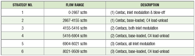
This will result in the following staging order and control modes (flows are approximate, not all Centacs can play all roles):
Energy Efficiency Measure #2 (EEM2) : Modify Compressors for Reduced Pressure
Energy savings for EEM2 are only possible if EEM1 has been previously implemented. This measure will modify the compressors for optimal performance in the pressure range that the system is already at, and for future reduced pressures. The management system will then automatically reduce compressor power as a result. This incremental reduction in energy is attributed to EEM2. This EEM only affects the compressor efficiency, not the control logic, flow or pressure. The existing centrifugal compressors were designed for far higher pressure than they are operating. In addition, they are two stage compressors, while new units of that size are three-stage, much more efficient. Since compressor replacement is quite expensive, we investigated two-stage compressor element upgrades to optimize performance as best as possible.
EEM2 Source of Energy Savings
The present compressors are optimized for 125 psig operation and are inefficient at lower than 100 psig. Since they are at the “choked flow” point at pressures lower than the design envelope, reducing pressure without modifying the compressors would not result in energy savings. The energy savings for changing the compressor elements comes from increased compression efficiency (scfm/kW) at all loads and all pressures, provided that the management system prevents the compressor from blowing-off.
EEM2 Specific Equipment Recommendations
- Replace the compression elements of all three Centac compressors with units that are designed for optimal performance at 80 psig, with the capability to operate up to 95 psig. This can be done either by replacing the impellers and diffusers or replacing the entire air-end assembly. There are two vendors who can do this, Air Relief (Gardner Denver) proposing the former and Ingersoll-Rand proposing the latter option. However, performance was not available for the impeller replacement option.
- Install two new flow meters, one at the discharge of Centac #1 and one for #2. Install a differential pressure transmitter for the existing orifice plate for Centac #3. Patch all three into the SCADA system.
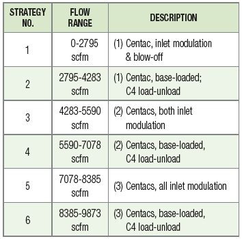
This will result in the following staging order and control modes (flows are approximate, not all Centacs can play all roles):
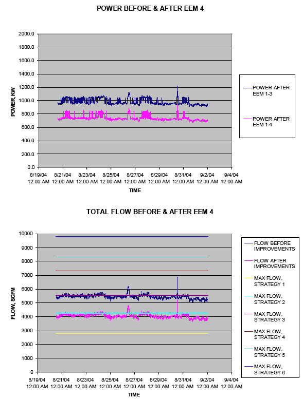
Energy Efficiency Measure #4 (EEM4): Reduction of Constant Blowing Compressed Air Usages
Energy savings for EEM4 are only possible if EEM1-2 has been previously implemented. EEM3 does not have to be implemented to have savings for EEM4. This measure will reduce compressed air flow only. The management system will then automatically reduce compressor power as a result. This incremental reduction in energy is attributed to EEM4.
EEM4 Source of Energy Savings
The elimination of constant compressed air flow for low velocity purposes such as cooling, diverting, and bubbling is the source of the savings. The additional power consumption required to run small blowers to do the same work is far less than the power saved due to the elimination of compressed air demands. Compressor power will be reduced because of the combined effect of the reduced flow and the previously implemented management system, which will be able to run the plant on one Centac and the 350 HP screw compressor much of the time if all these flow reductions are made.
EEM4 Specific Equipment Recommendations
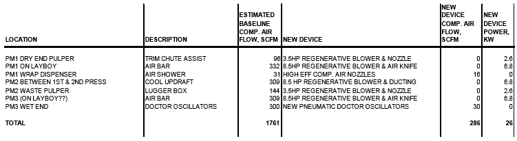
Table 2.1 Compressed Air Demand Reduction Opportunities
Baseline System Diagram
EEM1&2&4 Recommended System Diagram

Click here to enlarge.
Conclusion
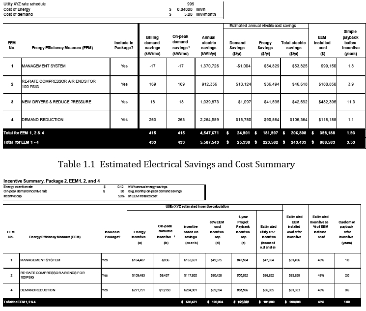
Table 1.1 below outlines the energy savings opportunities, the costs, and the ROI of all four EEM’s. The energy savings opportunity presented by EEM’s 1,2,&4 is 4.5 million kWh/yr, worth \$206,808 in energy savings per year.
The incentives in Table 1.2 are based on estimated energy savings and EEM’s costs documented in this report. The ROI impact of the incentives will be to lower the estimated project ROI from 1.9 years to 1 year. The actual incentive paid will be based on the final energy savings and EEM costs documented in a post-installation inspection report (completed by Utility XYZ). In both cases, here is how the incentive is calculated:
- Incentives for EEMs are first calculated individually as the lesser of the incentive based on demand and energy savings and 50% of EEM cost. If savings from lighting EEM’s exceeds 50% of the project savings (total of EEMs), incentives for lighting EEMs are adjusted.
- Next, the simple payback after incentive for the project (total of EEMs) is reviewed against the one year minimum. The simple payback after incentive is the EEM cost after incentive divided by the annual electric cost savings.
To be eligible for incentives, sign a Utility XYZ incentive agreement prior to signing purchase orders/contracts for installation.
The higher energy savings risk is with EEM4, because the EEM4 analysis is based on less certain numbers and the implementation might be incomplete. However, its cost is relatively low, so we strongly recommend implemention of as much of this EEM as possible, since this measure affects the entire project economics significantly.
Click here to enlarge.
For more information please contact Tim Dugan, P.E., Compression Engineering Corporation, tel: 503-520-0700, www.compression-engineering.com.


