A pharmaceutical product manufacturer spends an estimated \$137,443 annually on electricity to operate the oil-free air compressors in its compressed air system. The compressed air system operates well and is providing the level of purification required. Our team visited the plant and identified a group of projects which could reduce compressed air demand and reduce energy costs by \$42,248 – or 31% of current use.
The objective of this article, however, will be to illustrate the review we did of all the supply-side equipment. This includes the oil-free air compressors, dryers, filters, drains, oil-water separators and breathing air systems.
The Oil-Free Rotary Screw Air Compressors
The primary compressed air supply consists of three Kobelco, model KNW2-B/H, water-cooled, oil-free, two-stage rotary screw air compressors with 2-step (load/no load) capacity controls. All three units are rated for 215 horsepower at full-load. Their calculated full-load kW (at 125 psig) is 188 kW.
The sequence of operating the three Kobelco units are, first lead, second lag (or trim), and third standby. At the time of site review, the operating sequence of the compressors was #8 (newer Kobelco) in lead, #7 in trim and #6 in standby. With the appropriate maintenance, all three oil-free air compressors have operated reliably and met expectations.
The air system operates 8,760 hours per year. The load profile or air demand of this system is relatively stable during all shifts. Overall system flow ranges from 1,210 acfm during Monday through Thursday production, 807 acfm during Friday through Sunday production, and 741 acfm during holiday non-production periods.
The current units have capacity controls capable of translating “less air used” into a comparable reduction in electric cost. These controls will work effectively with the current piping and air receiver storage situation.
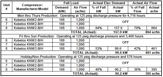
The system assessment identified sets of demand side efficiency projects able to reduce the demand on the air compressors. This translates into less energy used and will reduce the operating cost of the compressed air system. In the “compressor use profile” tables below, you can see how this allows the plant to turn OFF an air compressor and support plant operations, during all three shift load-profiles, with just one air compressor.
Here is a quick summary of the demand-side efficiency projects allowing us to turn OFF an air compressor.
- Repair thirtynine (39) tagged compressed air leaks
- Replace the open blow applications with engineered venturi nozzles designed to reduce the amount of compressed air used
- Repair vacuum generator control solenoid valve on line L04 instruction inserter
- Install level activated, electric or pneumatic actuated condensate drain valves on all three air compressors at the intercooler and aftercooler condensate traps
- Readjust moisture indicator sample air on both Hankison heatless desiccant dryers in Area 35 on the 2nd and 4th floors
- Repair large compressed air leak in a dust collector
Table 1: Air Compressor Use Profile – Current System
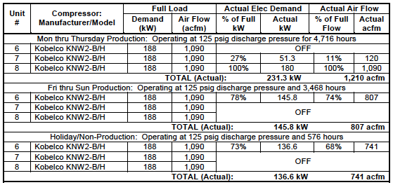
Table 2: Air Compressor Use Profile – Proposed System
The Compressed Air Dryers and Filters
The current compressed air drying system consists of several compressed air dryers located in different buildings at the facility. This includes refrigerated dryers and different types of desiccant dryers. All were functioning well. One unit had not been yet commissioned and we observed inlet piping too small in diameter, which we believe will lead to future problems. The appropriate pre and after-filters were installed and maintenance was changing them to maintain low pressure drops and air quality.
The Main Air Compressor Room
The main air compressor room has two Zeks 2000HSF cycling refrigerated dryers installed, capable of a 35°F to 38°F pressure dewpoint. At the time of the site visit, one dryer was operating and in satisfactory condition with no alarms or warnings present on the display screen. The other dryer was turned off and in manual standby.
Building A
A Zander ZEHD150 externally heated, heated-purge regenerative desiccant compressed air dryer is installed, capable of a -40°F pressure dewpoint. The unit is operating well.
The heated purge air is required for regeneration of the off-line tower, which means, dry compressed air from the outlet of the dryer is passed through a heating element, mounted outside the two towers containing desiccant, which heats the air to 350°F to 375°F, before entering the off-line tower. The heated purge air then is used to strip the moisture from the desiccant bed. The normal switching cycle for this type of dryer is 4 hours drying of the compressed air in the on-line tower and 3 hours, 15 minutes heated purge air with a 45 minute cool down period. During the cool down, the heating element is turned off but the purge air, or sweep air, still passes through the off-line tower during the regeneration cycle. The cool down period is needed to try and eliminate temperature and dewpoint spikes at switchover that are commonly associated with heated-purge desiccant dryers.
Building A Upper Floors
Two Hankison HHS40 heatless desiccant dryers are installed and in good working order. They are capable of drying the compressed air from -40°F to -100°F pressure dew point depending on the cycle option the customer has chosen. In this case the -40°F pressure dewpoint has been chosen. The cycle time between drying and regenerating the off-line tower are shorter than those times of the heated purge dryers. Similar heatless desiccant dryer cycle times typically are 4 minutes and 10 minutes between switching times and the pressure dewpoint selected.
During the site visit, the Hankison HHS40 dryers located on the upper floors both appear to be in satisfactory operation with no alarms present or displayed on screen. Both dryers have moisture indicators mounted on units that change color at the presence of moisture in the compressed air at the outlet of dryer. The moisture indicator needs to sample the compressed air leaving the dryer through an adjustable needle valve, or in this case, a petcock was used. The petcocks were open too far, only a very slight bleed is necessary for the moisture indicator to sample the air. Any more than a slight bleed is a waste of air. We recommend the petcocks be adjusted accordingly.
Building B Under Construction
The HCO Building has a dedicated VanAir HI400 internally heated purge, regenerative desiccant compressed air dryer capable of a -40°F pressure dewpoint. The heating elements are installed inside the towers. At the time of site review, this dryer was not in operation due to construction of the new Building B having not yet been completed. We observed, however, piping issues which we believe will create future compressed air quality issues for this dryer.
The current piping for the dryer is 1-1/2” Type L copper. With 1-1/2” Type L copper piping, the pipeline velocities will exceed the recommended pipeline velocities of 20-30 fps. This will lead to a pressure drop that could be excessive, and with the high compressed air velocities through the dryer, this could cause poor dew point performance and fluidization of the desiccant bed. Fluidization of the desiccant bed can cause dusting - which is when desiccant beads rub together and break down. This will result in dryer control air and after-filters plugging prematurely affecting service life, and purge mufflers becoming plugged with the desiccant dust which will effect regeneration of the off line desiccant bed.
Figure 1: Building “B” Dryer Piping – Current System
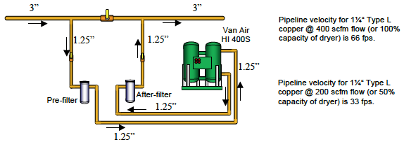
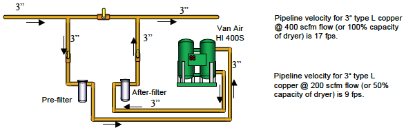
Figure 2: Building “B” Dryer Piping – Proposed System
The piping from the header to the filters and dryer is 1-1/2” Type L copper with a cross-sectional area of 0.0123. Below is the calculation that will show on the velocity of the compressed air going to and from dryers and filters:
400 scfm rated flow for the dryer
0.0123 cross-sectional area of Type L, 1-1/2” copper piping
8.2 compression ratio
60 seconds
Formula: (400 scfm / 0.0123 / 8.2) / 60 = 66 fps (feet per second)
At 66 fps of compressed air velocity going to and from the dryer and filter package, there is a high probability of a significant pressure drop which can lead to fluidizing the desiccant bed and desiccant dusting.
Decreasing the flow through the dryer to half its rated scfm capacity:
200 scfm (half dryer rated capacity)
0.0123 cross-sectional area Type L, 1-1/2” copper piping
8.2 compression ratio [(14.5 + 105 system pressure)(14.5)]
60 seconds
Formula: (200 / 0.0123 / 8.2) / 60 seconds = 33 fps
Even at half its rated capacity, the velocities the dryer and filters will see is 33 fps; still higher than the recommended 20-30 fps pipeline velocities.
By increasing the piping sizes from 1 ½” to 3”, we expect the pipeline velocity to drop from 66 fps to 17 fps (feet per second) at 100% of rated flow (400 scfm). At 50% of rated flow (200 scfm), we expect pipeline velocities to drop from 33 fps to 9 fps.
In summary, we recommended repiping the new Building B dryer with 3” Type L copper to eliminate the potential for excessive pressure drop through the dryer and filter package and eliminate the potential chance of fluidizing the desiccant bed which can lead to desiccant dusting and poor performance of the dryer.
Condensate Drains and Oil/Water Separators
The condensate drains on the dryers and filters are pneumatic, level-actuated type condensate drains and do not need to be modified. The air compressor condensate drains, however, purge or pop every 1 second and need to be replaced. We recommend replacing the condensate drains on the air compressors with level-activated drains - electronic or pneumatic actuated type. Ensure when installing the condensate drains, at the intercooler, that the moisture trap also has a check valve installed to prevent condensate from being pulled into the intercooler. When the air compressor is unloaded, the intercooler pulls a negative pressure during this period.
We estimate the drains on the air compressors to be using 3 cfm (per year). Replacing the six drains will save 18 cfm equaling \$2,219 in annual savings. We estimate the cost to acquire and install new drains to be \$4,800.
We always recommend condensate level-actuated electronic and pneumatic drains. Drains come in a number of varieties, including ones that receive the signal to open from a condensate high level and the signal to close from a condensate low level. These drains waste no compressed air and are the best selection from a power cost standpoint. Their reliability is usually many times greater than the level operated mechanical drains.
Plant personnel stated that the condensate goes to a centralized water treatment plant conforming with local regulations. If this is true, and if discharge condensate meets the requirements of the local water treatment facility, there is no problem. The use of oil-free air compressors also minimizes the likelihood of oily condensate (unless there are ambient hydrocarbons being ingested by the air compressors). The–Federal EPA minimum is 10 ppm but local wastewater plants may have lower ppm requirements to achieve environmental compliance and avoid environmental penalties. The compressed air condensate handling process at all plants should be reviewed to ensure environmental compliance.
Air Suitable for Breathing
An important issue to note is the Deltech Del-Monox breathing air system needs to have both the catalyst cartridge and final filters replaced. Both catalyst cartridge and filters are past the recommended service interval. The CO2 monitor mounted near the Del-Monox breathing air system shows 0.0 ppm CO and has been recalibrated.
Compressed air coming directly from air compressors and from standard compressed air dryers, does not comply with OSHA breathing air standards such as the latest versions of OSHA 1910.134 – or with the appropriate Canadian CSA Standards. One should also consult with local authorities for any local regulations.
Breathing air systems, like the Del-Monox purification systems are designed to remove excessive moisture, solid particulates (dust/dirt), oil and oil vapor, carbon monoxide, and hydrocarbon vapors commonly found in ordinary compressed air.
Conclusion
The bulk of our work, at this pharmaceutical plant, revolved around the compressed air use-reduction projects. Compressed air purity, if over-looked, can cause business-impacting product-rejects, production down-time, and even liabilities. It’s extremely important, therefore, to regularly inspect and examine all aspects of a compressed air purification system, from the smallest condensate drain to life-sustaining breathing air systems!
For more information, contact Don van Ormer, Air Power USA, at don@airpowerusainc.com or visit www.airpowerusainc.com.
To read more about Pharmaceutical Industry Applications, please visit www.airbestpractices.com/industries/pharmaceutical.


