Compressed Air Best Practices® Magazine interviewed Mr. Warwick Rampley, the National Sales Manager for Sydney (Australia) based, Basil V.R. Greatrex Pty Ltd.
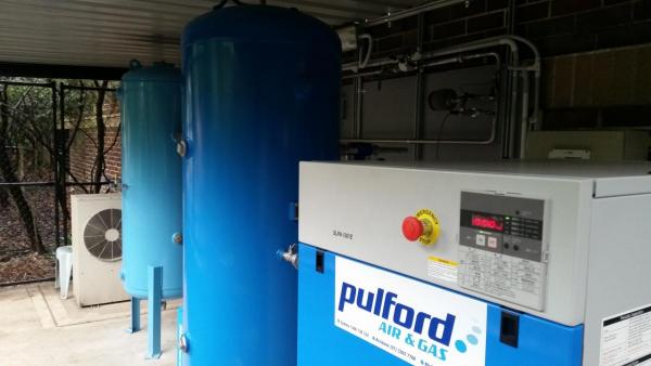
An oil-free air compressor, refrigerated and membrane dryers, filtration, wet and dry tanks provide “Class Zero” compressed air to this system.
Good afternoon (actually good morning), thank you for bringing this application to our attention!
Good morning. You are very welcome. This was a special job we thought your readers might find interesting. It’s not every day one is asked to deliver a system able to provide both a reliable compressed air dew point of -80°C (-112°F) and high purity nitrogen. We work with some excellent technology suppliers and have engineered a rather interesting system.
Although our firm was founded in 1919, this application is one of the most demanding we’ve encountered. Basil V.R. Greatrex is a unique company as we focus only on compressed air measurement, compressed air quality and compressed air efficiency. We had the right skill sets for this job!
What is a NMR laboratory and what kind of test equipment is using compressed air and nitrogen?
In layman’s terms, a nuclear magnetic resonance (NMR) spectroscopy facility analyzes samples to identify their components at an atomic level. This facility is located in the Sydney region and utilizes Bruker AVANCE spectrometers featuring a NMR superconducting magnet – a complex system producing a very strong, homogenous, and stable magnetic field required for NMR. The magnets are actually eight (8) feet tall and up to 5 feet in diameter. The magnets are kept in liquid helium at temperatures of around -200 °F. The magnetic forces are so strong that there are strict guidelines limiting human exposure to the area – even a couple floors above the machine!
Compressed air and nitrogen are two key utilities, used by the magnets for cooling and moving samples in and out of the machines. The gas supply is determined by the electrical frequency of the system. The AVANCE instruction manual states:
- 200-400 MHz: Compressed air
- 500 MHz: Nitrogen gas with 95% purity
- 600-750 MHz: Nitrogen gas with 95% purity
This laboratory has three NMR systems outfitted with BCU-II cooling units operating at different frequencies (a 400 MHz system, a 500 MHz system, a 600 MHz system) installed. This is why we must supply both compressed air and nitrogen.
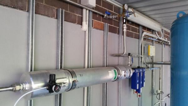
The hollow fiber membrane dryer provides a pressure dew point of at least -80°C (-112°F). Prefilters ensure no moisture, dust or oil vapor/liquid contaminate the membrane dryer.
What are the compressed air specifications for the AVANCE system?
The Bruker instruction manual and “site guide” has quite a chapter titled “Utility Requirements” on this topic. Here is a summary of the top-line compressed air specification.
- Water Content: -80°C (-112°F) pressure dew point
- Oil Content: < 0.005 ppm (0.005 mg/m3)
- Solid Impurities: Filters should retain a minimum of 99.99% of particles < 0.5 micron in size or larger. Note: client specified a higher purity than this.
The Bruker site guide sets out the standards based on the size/type of NMR equipment being used and the cooling unit fitted. In this case there are 3 magnets of different sizes, all are fitted with a BCU-II cooling unit which cools compressed air to around -80°C (-112°F). Bruker specifies the compressed air must have this dew point as a minimum level to avoid damage to these three very expensive units estimated to be worth around \$4 million AUD ($3 million U.S.). A sample may be spinning at 100,000 rpm and if it loses its gas supply, it may self-destruct.
The site guide also specifies an oil content of <0.005mg/m³ to avoid contamination of the samples and false positives on the results. Particles are a much lower standard requiring only <0.5 micron, however the site specified that given the other stringent requirements they did not want to risk their equipment and went for better than ISO8573.1:2010 Class 1. This effectively made the system a fully compliant Class 0 System.
Please describe the air compressor specification and what was installed.
The Bruker utility requirements specify an oil-free air compressor. It should be a membrane or Teflon coated piston or scroll air compressor with a fine dust inlet filter. To meet the specification, we worked with a local company, Pulfords Air and Gas, who provided us with an excellent oil-free rotary scroll (Anest Iwata) package featuring four scrolls each powered by a 4 horsepower (5.5 kW) electric motor. It’s packaged in a single cabinet and the controller rotates through each air end to evenly distribute working hours. It also will automatically start and stop each air end depending on the compressed air demand.
Describe please the compressed air drying system.
Every part of the drying and filtration system is staged to give the best possible efficiency and results. The scroll compressors can produce very hot compressed air due to the elevated ambient temperatures we often experience in Sydney summers. We can see air compressor outlets at up to 25 °C (77 °F) above ambient temperatures, so they can reach 60°C (140 °F). We even had one day this summer where we hit 48°C (118 °F). Therefore, there is an oversized “wet” receiver allowing the compressed air to cool to more manageable levels while also condensing and separating out a large amount of the entrained moisture. This “wet” receiver is fitted with a Bekomat zero air-loss electronic drain. All of the equipment, including the zero air-loss condensate drain, is wired into the monitoring system so alarm conditions can be instantly detected - we’ll get into that later.
Benefits of Desiccant Dryer Dew Point & Purge Control - Webinar RecordingDownload the slides and watch the recording of the FREE webcast to learn:
|
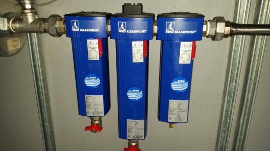
Another challenge to purity is the fact there is a large car park located near the air compressors - so there are plenty of ambient hydrocarbons being ingested. The compressed air is filtered by a 1 micron filter, after the wet receiver, and then enters a refrigerant dryer designed to cope with the high ambient temperatures we discussed. From there it is filtered further by a filter pack with a .01 micron filter, an activated carbon tower, and finally a .01 micron dust filter.
Special considerations are also made for the piping and fittings so no contaminants are introduced here. A local firm specializing in piping systems, Superior Engineering Solutions, provided tremendous technical assistance with this portion of the project. We have seen installations, in the past, where the wrong kind of teflon tape on fittings would cause dew point degradations of 15 degrees! This whole system uses welded stainless steel pipe. We do use a special type of teflon tape where necessary.
This system removes as many contaminants as possible before we get to the final stage. Membranes dryers can tolerate zero liquids or solid particles. This is why this pre-treatment system is so important.
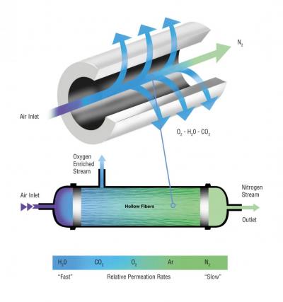
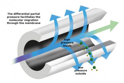
Using Membranes to Generate Nitrogen from Compressed AirThe Nitrogen Generator uses semi-permeable, hollow-fiber membrane technology to separate and recover nitrogen from compressed air. Atmospheric air generally contains 78% nitrogen, 21% oxygen and 1% other gases. The membrane uses the principle of selective permeation to produce high purity nitrogen. Conceptually, the hollow-fiber membrane is like a porous drinking straw. Compressed air is forced through the center of the “straw”. Each gas has a characteristic permeation rate, which is a function of its ability to dissolve and diffuse through a membrane. Oxygen is a "fast" gas and is selectively diffused through the membrane wall while nitrogen is allowed to travel along the inside of the fiber, thus creating a nitrogen rich product stream. The oxygen-enriched exhaust gas, or permeate, is vented from the membrane separator at atmospheric pressure. The driving force for the separation is the difference between the partial pressure of the gas on the inside of the hollow fiber and that on the outside.
A typical membrane separator contains thousands of fibers, which are bundled and encased at both ends in epoxy resin. The ends of the bundles are cut which leaves the fiber bores open on both ends, allowing the gas to travel from one end to the other. The bundles of fibers are enclosed in a suitable casing. The casing protects the fibers and routes the gas properly from feed to product end. In the membrane separator, compressed air flows down the inside of hollow fibers. "fast" gases - oxygen, carbon dioxide, and water vapor, and a small amount of "slow" gases, pass through the membrane wall to the outside of the fibers. These are collected at atmospheric pressure as the exhaust permeate, or waste, stream and should be vented to a safe location. Most of the "slow" gases and a very small amount of the "fast" gases continue to travel through the fiber until they reach the end of the membrane separator, where the product nitrogen gas is piped to the application.
Images provided courtesy of Titus Air Systems and PRISM® Membranes, Air Products and Chemicals, Inc. |
The membrane dryers drive the dew point down to -80°C (-112°F)?
Yes. The compressed air is now dried further using a specially designed membrane dryer supplied to us by Titus Dryers. The membranes are able to drop the dew point to actually around -85°C (-121°F) where we see it stabilizing. Membrane dryers use no electricity and are incredibly effective and reliable at separating gaseous moisture from the compressed air stream. The differential partial pressure facilitates the molecular migration through the membrane as the faster-moving moisture molecules seek the low-pressure port (sweep air) while the compressed air continues to travel through the insides of the hollow membrane fibers.
Finally there is a large dry air receiver installed so system demands do not impact the flows going through the drying and filtration system. The compressed air then enters the lab environment where it is delivered directly to one of the magnets after passing through one last filter set - just in case of equipment failure upstream. All the magnets are regulated at the point of use and receive a very steady pressure of 6 bar (88 psi).
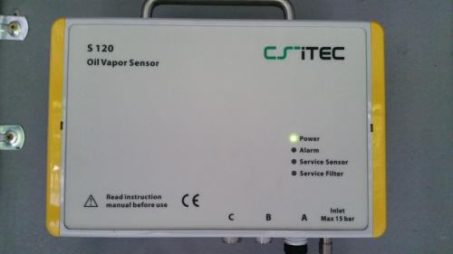
The system is fully instumented to measure oil vapor, particulates, nitrogen purity, dew point, pressure and kW consumption.
How does the nitrogen supply work?
The other two magnets require nitrogen. We take a portion of this low dew point and purified compressed air and pass it through a TN2 nitrogen membrane generator supplied by Titus Air Systems. This unit provides a purity of around 99% where the specification calls for better than 95% purity. For now, the client wants to operate with this margin of safety. We may revisit the 99% purity level in the future in order to utilize less compressed air. The nitrogen is then stored in a small nitrogen receiver and delivered to the magnets through a filter set.
How is the compressed air system – particularly the dewpoint monitored?
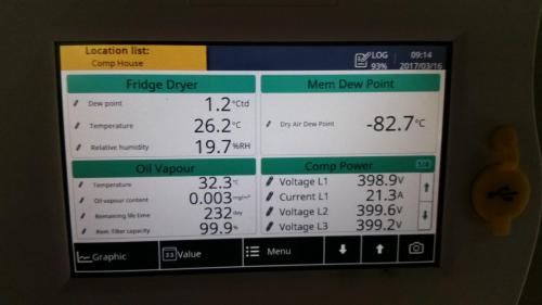
The system is monitored using a Suto (Formerly CS-iTec) S331 local interface/data logger that feeds information through to their software which can then be monitored anywhere in the world in real time. There are sensors on everything. The air compressor has a local display and a data logger providing power monitoring and ambient and outlet air temperatures.
Pressure sensors are placed at the wet and dry tanks, on all pre-filters and after-filters, and before and after both the refrigerant and the membrane dryers. Dew point sensors are installed after both the refrigerant and membrane dryers. Oil vapour and particles are measured and monitored. Nitrogen purity and pressure are monitored. Flow before and after the membranes is monitored. All the sensors are supplied by Suto. The system is automatically shut down and falls back to a boil-off nitrogen systems if it falls out of specification. Boil-off nitrogen is too expensive to use, as the continuous supply, hence forming part of the backup system.
It’s an amazing system. Any closing comments?
To conclude, the system has a measured and monitored pressure drop of <0.3bar from compressor to end user, the oil contamination is less than 0.003mg/m³ and particles are around 300 or less for the 0.1-0.5micron range and 0 for everything above that. The pressure dew point is -85°C (-121°F). It’s really been interesting to have the opportunity to work with our vendors and with the client to see just how tightly a compressed air and nitrogen system can be controlled and managed.
Thank you for your time.
For more information, contact Warwick Rampley, National Sales Manager, Basil V.R. Greatrex, at email: warwick.rampley@bvrg.com.au or visit www.bvrg.com.au.
To read more about Laboratory Applications, please visit www.airbestpractices.com/industries/pharmaceutical.


