Supply-Side Overview
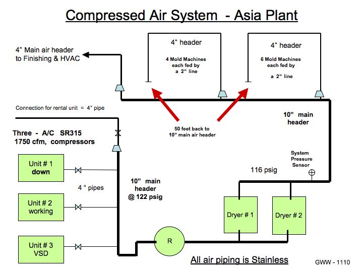
This plant was built and started-up in 2006. It has three 315 kW Atlas Copco ZR315 rotary screw ( non-lube ), water-cooled air compressors. One unit has a variable speed drive and it is used to control air pressure in the main 10” header that supplies the adjacent critical manufacturing process. A multiple compressor control system was included with the project. The installation was quite impressive. The equipment is robust and maintenance is very good.
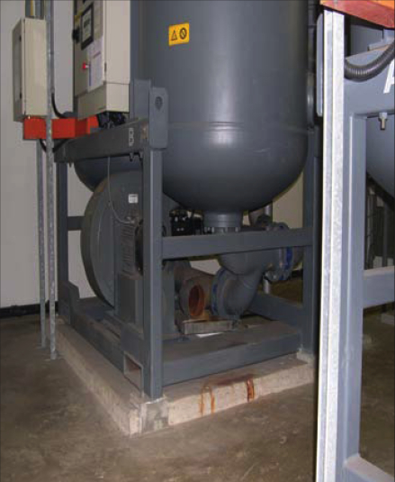
The air compressor motors operate at 1,450 rpm (with 50 cycle power) providing about 1,700 scfm each. A 1,500 liter receiver tank supplies two 1,800 cfm regenerative desiccant air dryers installed in parallel. The dryers have an electric heated blower that uses 70 cfm of compressed air as part of the regeneration valve-sequencing operation. The facility operates on a 24-hour, 7 day a week schedule. Two machines are normally in service.
We conducted a comprehensive compressed air system assessment. Opportunities to improve the system were found in the main piping system, in reducing pressure losses in the mold machine piping, and with the high ambient temperatures found in the compressor room. We estimated energy savings of 403,500 kWh per year for a power savings of \$65,000 per year. The total projects costs were \$48,000 for a simple ROI of nine (9) months.
Pressure Swings in the Main Piping System
The compressors were operating at 120-124 psig – a pressure well above the system pressure necessary for this type of facility. All crucial process equipment is designed to operate satisfactorily at 84-88 psig inlet to the machine regulators.
A “defective product” recall had recently resulted in raising system air pressure from a nominal 108 psig to 118 psig. We determined that the air compressors should be able to operate at 100-104 psig discharge pressure and adequately provide a minimum 90 psig in the 2” main lines that supply each of the ten critical-process molding machines.
Line pressure drop from the compressor room air dryers to these machines was calculated to be only 2-3 psig. When we also include filters and manifold valves, we saw a 5-6 psig pressure drop. This air treatment system is performing very well – providing high quality air with an appropriate pressure drop.
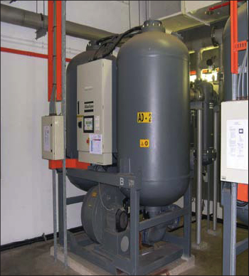 |
The heated desiccant air dryers, with pre- and after-filters provided a reliable pressure dew point of – 40 F, with a low system pressure drop, for this pharmaceutical plant. |
The two main 4” air lines (located directly off of the 10” main header) supply the manufacturing bay with six molding machines on one loop and four machines on the second loop. Two additional machines are planned for the second area in 2011.
We determined that, due to a semi-loop configuration of these 4” air lines supplying the molding machines, it required only 50 feet of additional 4” pipe on each loop to connect back into the 10“ main header. This would eliminate all doubt of machines at the end of the loop experiencing low pressure. Due to the additional planned machines, plant personnel agreed to proceed with this modification. The cost for the piping changes was \$9,000.00.
Process air demand was generally very uniform. Each key molding process machine uses between 75-100 scfm. Other plant compressed air uses (finishing, HVAC, maintenance, leaks, etc.) were determined to have no significant surge conditions.
Nevertheless, the main 10” air header was experiencing pressure swings of 5-6 psig on a regular basis. We determined that the swings were due primarily to the be compressed air dryer tower regeneration sequencing valves and the slow-responding air compressor pressure controls. The air compressor load controls (both the direct drive units and the VSD unit) were not programmed to be able to maintain the system header pressure within the expected 2-3 psig range with a steady plant air load of only 2200-2400 scfm (with two units in service).
To solve this, the decision was made to hire Atlas Copco service personnel to inspect the equipment and re-configure the air compressor and air dryer control systems and valving. The estimated project cost was \$18,000. Please note that this compressor control investment was necessary to capitalize on the system improvements detailed further on in this assessment.
Pressure Drops in the Mold Machine Piping
The reported low air pressure condition in a key zone of each molding machine was determined to be due to local piping restrictions at the main air regulator valve. A ¾ inch size plastic air hose (with ½” I.D. pipe nipples) connected the 2” air supply pipe to the 1¼ ” size regulator on the machine. We recommended changing this 18” long hose to 1½” size on each machine and to also use less restrictive hose/pipe fittings. The cost was \$200.00 for each machine for a total project cost of \$2,000.00.
Each one of these molding machines was experiencing a pressure drop of 16 psig due to the restrictive hose/piping arrangements! A system pressure reduction of 16 psig (from 116 psig nominal to 100 psig) equaled an energy savings of eight percent (8%). The reconfigured air compressor controls were able to capitalize on the lower pressure requirements and deliver an estimated air compressor energy savings of 293,400 kWh per year. This equals approximately \$47,000 of air compressor motor power savings per year.
Reducing Ambient Temperatures in the Compressor Room
Located in Southeast Asia, this plant experiences average annual ambient outdoor temperatures ranging from 850 to 950 F. Rain can be a daily occurrence for half of the year. Heat and humidity are serious issues for air compressor and air dryer efficiency in these conditions.
The compressor room was an enclosed concrete building with the main electrical MCC switchgear adjacent to the equipment. The large roll-up access door was kept closed and locked (safety rules). Good-quality supply and exhaust air ducts can be provided. The ambient air supply, however, was hot outdoor air. The air compressors are water cooled, thus air line piping temperature was not an issue. However, the compressor room ambient temperature was over 1000 F on a continuous basis.
The goal was to reduce the average compressor intake temperature by 300 F! We accomplished this in three steps.
- Remove heat generated by the air compressors by modifying the exhaust ventilation ductwork in the compressor room by connecting directly to each air compressor and capturing the 1400 - 1450 F hot air from the compressor enclosures at the top of each unit. Remove this HOT air from the compressor room by utilizing the existing room exhaust duct system.
- Remove heat generated by the heated desiccant air dryer by modifying the air dryer regeneration exhaust piping (hot regeneration air issues) and by insulating the tops of the towers. Currently, the hot, humid regeneration air is being exhausted into the compressor room. We will remove this exhaust air by connecting it to the existing room exhaust duct system. We will also insulate the upper parts of the air dryer towers which reach temperatures of 2000 - 2100 F when in regeneration mode. These two actions will reduce ambient heat and humidity inside the compressor room so the machines can operate more efficiently.
- Connect the room ambient air supply unit into the adjacent HVAC machine room that has an ambient of 750 F (due to numerous large chilled water lines and AHUs in the room).
The total air duct modification costs for the three air compressors is estimated at \$15,000. The cost for 30 feet of 10“ insulated steel pipe discharge pipe and a thermal insulating mat on top of each dryer tower is \$4,000. Achieving a 300 F colder ambient in the compressor room equals a three percent (3%) air compressor motor power savings. This equals savings of 110,100 kWh and \$18,000 per year.
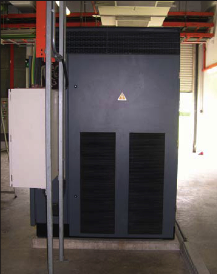
The air compressors were experiencing air intake temperatures above 100 F. Installing exhaust ventilation ductwork on the air compressor helped lower ambient temperatures in the compressor room. |
The desiccant air dryer was exhausting 230 F hot, humid air into the compressor room during the 4-hour regeneration cycle. |
Summary
A compressed air system assessment of this type is not unusual for us. All of the supply-side equipment (air compressors and dryers) was operating well and was well maintained. The over-all system had also been given considerable thought and investment.
The primary opportunities for improvement lay in reducing the 16 psig of pressure losses found in the hoses and piping in each of the molding machines. The second area of opportunity was to reduce the ambient temperatures in the compressor room by 30 F. Once these things were accomplished, modifications in the compressor controls were required to capitalize on the potential energy savings. We estimate energy savings of 403,500 kWh per year for a power savings of \$65,000 per year. The total projects costs were \$48,000 for a simple ROI of nine (9) months.
For more information visit www.jogarenergy.com.
To read more pharmaceutical industry articles, visit www.airbestpractices.com/industries/pharmaceutical.


