Overview
Kneeling modules are quickly becoming the centerpiece of accessible vehicle equipment. This trend began with passage of the Americans with Disabilities Act (ADA) in 1991. Prior to the ADA, about 40% of all transportation vehicles were accessible to persons with disabilities. Today, over 50% of a fleet owner’s vehicles (e.g., public transit authorities and school districts) must be compliant with Title II of the Act, which explains the extent to which public transportation services are affected and how the Department of Transportation (DOT) will regulate requirements. By 2012, 100% of the vehicles in these provider’s fleets must be accessible to persons with disabilities (except providers that meet the small business definition). For this reason, bus OEMs require that these modules are durable, compact and lightweight while withstanding harsh elements. Functionally, the modules must be able to deflate air bags on demand and lower the bus quickly to ease passenger entry. Conversely, the module must then inflate the air bags at a similar pace, enabling the bus to resume its scheduled route. Kneeling modules are designed for OEM installation on new vehicles and to retrofit older model vehicles.
Extensive testing must be performed to ensure that kneeling modules are reliable and durable enough to meet the demands of the Bus & Coach Industry. A typical bus kneeling application could see a module mounted to the exposed underside of a NYC transit bus where hundreds of stops are made per day in wintry conditions with temperatures reaching extreme negative degrees. If the kneeling module fails to perform as required, needless time delays result and passengers endure unnecessary difficulties in entering/exiting the bus. If the circumstances are severe enough, passengers may be denied entry on the bus due to their physical limitations that require the kneeling. This white paper addresses the most common types of failure modes regarding bus kneeling, along with the causes for these failures, and therefore what design considerations need to be incorporated into a kneeling module to prevent these failures from occurring. Extensive testing illustrates how these design criteria ensure optimum performance in a variety of harsh conditions while maintaining the durability and reliability of the module by minimizing component failure.
Failure Modes and Causes
What is a failure? If a product or system does not meet or exceed a customer’s expectations in regard to performance, service, and/or quality, then a product failure results. The two most common failure modes for kneeling modules are life cycle failures and leakage failures. A Life Cycle Failure is when the product does not perform as promised. This is the most extreme failure mode. Many transit authorities and fleets will disable the vehicle’s kneeling function as a result of continual inconsistent performance. This failure mode can occur for various reasons, from solenoid failure, to poppet or spool valves not shifting, to spring breakage. In the case of Leakage Failures, the product continues to perform, but excess air is wasted because of system leakage. This is considered a secondary failure mode due to the lack of severity. Leakage failures can result in excessive noise either at the point of the leak, or quite often from the air compressor operating at a higher than normal cycle rate to maintain air system pressure. Not only is the noise pollution an issue for the driver and passengers, but more importantly, the wasted energy results in increased operating costs for the bus owner through more frequent maintenance and downtime from excessive operation. It should be noted that leakage failures that continue for an extended period of time can often escalate to more severe life cycle failures.
The three most common causes of kneeling module failures – whether life cycle or leakage – are Temperature, Contamination, and Vibration. The following section details these three major causes of failure, along with summary highlights from a series of tests conducted to simulate these real world applications with side-by-side comparison of multiple modules.
Failures Caused by Temperature
The most critical kneeling module performance requirement for bus OEMs and end-users (e.g., fleet owners) alike is to function properly in a wide range of temperatures. Both high and low temperatures cause failures. High temperatures can induce life cycle failures by causing seals to soften and wear too quickly. Solenoids failures can also occur due to overheating if the module sees temperatures in excess of 100°C. Low temperatures, however, are by far the most common cause of both leakage and life cycle failures and, therefore, a more critical element around which to design a module.
Kneeling systems must be able to meet the industry standard requirement of performance at -40°F (-40°C). When temperatures reach extreme negative degrees, seals will begin to harden and stick causing a “no shift” failure mode to occur. When seals harden they are also more susceptible to becoming cut as the valve operates, thus causing a leakage failure. Eventually the damage will be so great that a life cycle failure will result. Seal shrinkage due to extreme cold can also cause the valve to not seal properly, thus resulting in a leakage failure.
Dryers not installed and maintained properly in the air system that operates the kneeling module can also cause life cycle failures. Water in the air lines freezes when the temperature falls below 32°F (0°C) and causes the internal components of the module to no longer function because they have frozen together. Regardless of a kneeling module’s ability to operate in extreme temperatures, an effective system must be provided (and maintained) to dry the system’s compressed air. Unless moisture is removed from compressed air, it will condense as liquid water in the lines and cause line and component damage when it freezes. Even if freezing doesn’t occur, water in the compressed air stream can wash away needed lubricants in cylinders and valves causing equipment malfunctions and premature component failure.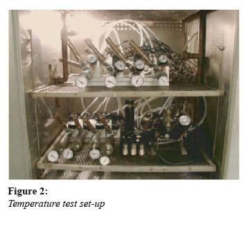
Many kneeling system manufacturers claim that their product will perform in extreme temperatures, specifically -40°F. The question is how well? The only way to know for sure is by conducting a series of low/high temperature endurance tests that best simulate the real world conditions the module will be exposed to during operation. This test was performed on 10 kneeling modules.
Testing Method – Using 10 kneeling modules, 24 temperature tests were conducted. Six 3-station 24VDC and four 4-station 24VDC units were used for this test. With 100-psi air to each module’s supply port, 6.5 cubic inch volume chambers connected to the right airbag & leveling valve ports, and 3 cubic inch chambers to the left airbag & leveling valve ports, the tests measured for leaks under the following conditions:
- Room temperature
- Low temperature and high temperature profiles; with and without a dryer
- Six-to-eight day duration cycling tests at different temperature profiles
- Sticking tests at different temperature profiles
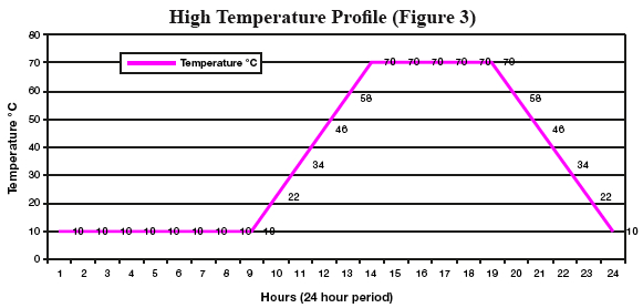
This extreme hot temperature cycle simulates summer operation.
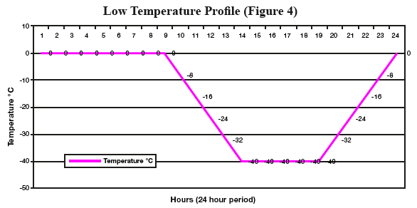
This extreme cold temperature cycle simulates winter operation.
As noted, the hot temperature profile shown in Figure 3 was used to simulate summer operation. The cold temperature profile shown in Figure 4 was used simulate winter operation over a 24 hour period. The temperatures ranged from -40°F (-40°C) to 158°F (70°C). All supply ports for each module were connected to a distribution manifold to allow total leakage to be checked individually by a flow meter. A Programmable Logic Controller (PLC) was used to time the exhaust from the modules to minimize air pressure spikes inside the chamber. The PLCs were programmed to both automatically cycle the modules during normal testing or provide for manual control so that individual solenoids could be activated for leakage checks.
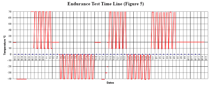
The cycle rate used for testing was 34 cycles per minute and the test duration equated to 20 years of intensive operation: 2,102,400 cycles calculated; assuming one (1) complete kneeling cycle every five (5) minutes for a non-stop duration of 20 years. Shown below in Figure 5 is the profile for the cycle testing as the modules were continuously exposed to either the summer or winter profile. Both seasonal profiles were alternated weekly throughout the entirety of the life cycle testing.
An operational cycle for a 4-station unit:
- Supply, left and right airbag solenoids all on-
- Supply, left and right airbag solenoids all off -
- Exhaust, left and right airbag solenoids all on-
- Exhaust, left and right airbag solenoids all off-
An operational cycle for a 3-station unit:
- Supply, left airbag solenoids both on-
- Supply, left solenoids both off-
- Exhaust, left airbag solenoids both on-
- Exhaust, left solenoids both off-
Test Results – At room temperature, all of the modules tested were leak free when solenoids were de-energized - normal ride mode for the bus. When filling airbags, all modules were also leak free. During the airbag exhausting phase, one 4-station module had excessive leakage due to an o-ring failure at the 800,000 cycle point (approx. 8 years). Upon completion of the cold and hot sticking tests, with the restoration of warmer temperature, all modules were leak free. All modules continued functioning during low temperature testing, but developed excessive leaks. As the test progressed, most of the low temperature leakage stopped when temperatures rose. Wear on the over-molded poppet (Figure 6), along with the poppet o-rings was minimal. Upon further examination after the completion of the test, it was discovered that the failed o-ring was due to a molding defect in the product and not as a result of the cycle testing.
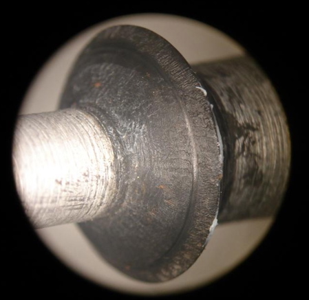
Figure 6: Over-molded poppet removed from kneeling module after 2 million cycles
Failures Caused by Contamination
While not as severe a factor as temperature, contamination is also a leading cause of failures of kneeling systems on busses and coaches. Contamination from weather and environmental conditions causes damage and potential failure to both the external and internal components of a kneeling module. External contamination to the module can eventually lead to leakage failures. Dirt and dust, water, salt, rocks and other debris can cause extensive damage to a kneeling module. For this reason it is absolutely critical to design a system that will protect the module against these harsh elements. Internal corrosion is usually caused by contamination from water and/or oil from the compressor. This type of contamination can often lead to more severe life cycle failures. As mentioned above, if the system does not use a dryer to control moisture build up in module components and air lines, it can cause damage if the water either freezes or washes away lubricants needed to ensure that the module functions properly. Oil from other components of the air system can also cause damage to the module. This occurs when the oil has a reaction with different internal components. Seals suffer the most significant damage. A chemical reaction can damage seals significantly, thus reducing the life of the kneeling module.
Testing Method – For this series of tests, four kneeling modules were used to measure the module’s performance in environments that cause contamination and corrosion – both externally and internally. The specific tests performed on these modules were Salt Spray Testing and Oil & Moisture Injection Tests.
During the Salt Spray Test, four kneeling modules were placed in a salt fog chamber. The chamber was filled with a 5% salt and water solution. Humidity and heat were added throughout the test. The modules were soaked in the salt mixture for 200 hours and, following completion of the test, were function tested one final time. A second salt spray test was also performed under the same test conditions, but specifically on the kneeling module solenoid. In order to isolate the solenoid from the rest of the module during the testing, the second test used transportation-rated inline solenoid valves that utilize the same solenoid technology.
To perform the Oil & Moisture Injection Test, four kneeling modules were connected downstream from a lubricator. An oil/moisture mixture was injected into each module at a rate of 3 cc per hour. The modules were then cycled at 18 cycles per minute continuously for 48 hours. Following the initial 48 hours, the modules were then tested for full function capability, as well as, all potential full system leaks using an upstream flow meter.
Test Results – All four kneeling modules functioned properly following the first 200-hour Salt Spray Test. Each unit showed some oxidation around the solenoid valves and steel pipe fittings; but there was no oxidation on aluminum parts or internal components (See Figure 7). Results of the second test showed that both solenoid and solenoid pilot operators were still operational after 500 hours of salt spray testing. The solenoid mounting screws were heavily oxidized at the completion of the soak test. See Figure 8 below.
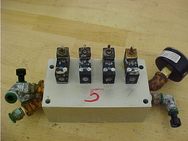
Figure 7: Kneeling Module after Salt Spray Testing
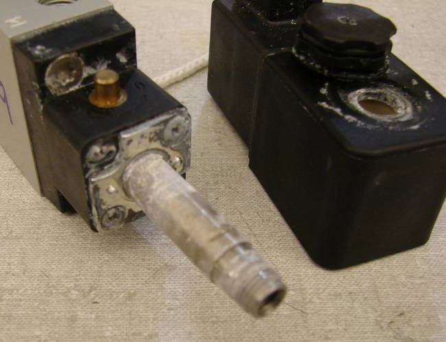
Figure 8: Salt Spray Testing performed on pilot operator and coil
The Oil & Moisture Injection Test proved to be more demanding than the Salt Spray Tests. Two of the four kneeling modules functioned properly throughout the entire test, but the remaining two units stopped functioning after 14 hours of cycle time. At the end of the cycling, however, all four units functioned properly and did not leak. A cause for the two units failing to cycle the entire test could not be determined.
Failures Caused by Vibration
Vibration is the third major cause for leakage and lifecycle failures in kneeling modules. If not designed properly into a product, fasteners, springs, connectors, fittings, and other components have the potential to vibrate loose, break, or general component failure can result due to shock G vibration force.
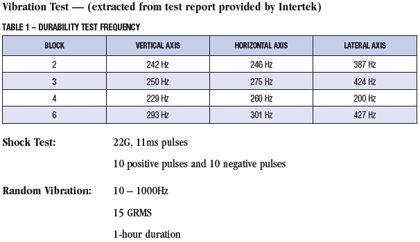
Testing Method – Four 4-station modules were mounted on a vertical axis. Four bolts were used to attach the module to a fixture; 120 in-lbs of torque was applied. A five (5) minute resonance sweep was performed to determine peak frequency (10-2500Hz at 2Gs) and then a durability test for 100,000 cycles was performed at that frequency. These procedures were then repeated for both horizontal and lateral axes. See Table 1 below.
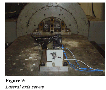
Test Results – All four modules tested and all of the solenoids were fully functional after each test. Additionally, module number four was subjected to additional shock and random vibration in each axis. Following each profile the solenoids were checked for functionality. The test proceeded axis by axis in the following sequence: resonance sweep, durability, function check, shock test, function check, random vibration, and a final function check. The block worked properly after each step. Functional checks were performed by using shop air (nominal 90 psi). The solenoids were cycled manually to permit audible detection of any malfunction (Figures 9 and 10). The supply valve on the module was opened, the left valve checked, followed by the right valve. The exhaust valve was then opened to release trapped air.
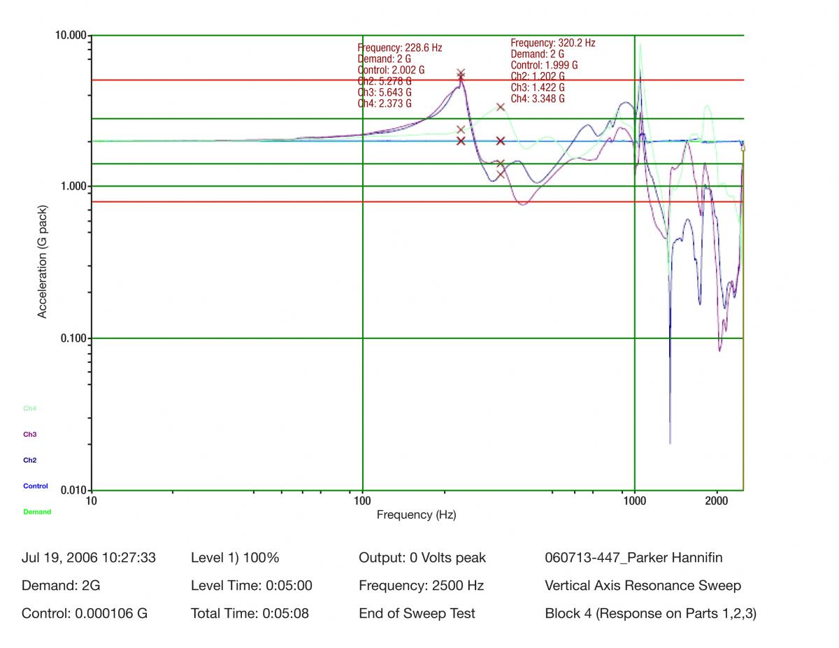
Acceleration Profile (Figure 10)
A Kneeling Module Designed for Reliability and Durability
After careful examination of all modules used for each series of test, the following is a list of the key design considerations identified that directly contributed to the successful results discussed in the previous section.
Single-Piece Anodized Body – This critical component of the module is the core to the entire design. The kneeling module’s anodized body, along with other internal aluminum components, allows it to withstand harsh environments. Much of the success of the modules tested was directly influenced by the anodizing process these modules underwent during fabrication. Other observations - Precision machined internal parts, as well as, the stainless steel return spring, designed specifically for the transportation industry, also contributed to the testing success, and ultimately ensuring a long operating life in the field. A single body design allowed for the flexibility to build three or four station modules from one component. A one block design for both versions also resulted in the same bolt hole pattern and connections for test setup. As a result, labor costs for assembly can be reduced in the field due to fewer components, connections and tubing. Fewer connections equate to fewer leak paths than with multiple valve assemblies and fewer components to purchase. The module size was also an added benefit as it is easily able to fit in tight spaces. Also, the module was designed so that components can be easily replaced if necessary.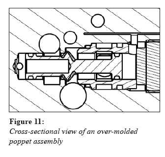
Over-Molded Poppet Valve Design – Although listed second, this key design point is certainly just as important as the first, if not more. The life and performance of the kneeling module rests almost entirely on the performance of this component. The quality of design and manufacturing of the poppet valve can both influence the life cycle failure mode, as well as, the leakage. The poppet assembly was also the most affected by all three failure mode causes identified (temperature, contamination, and vibration) and, as a result, was the most affected component during all the various tests conducted. Observations - This low-temperature compound, precision ground poppet design, versus a spool design, was much better suited for harsh environments. A special over-molded rubber was used on the valve, which is suitable for both low and high temperature applications, ranging from -40°F to +158°F. Since the valve was designed with fewer components, there were less possible failure modes as a result. Performance wise - the valve’s higher flow rate allows the bus to raise and lower at a faster pace compared to other modules observed.
Low-Temperature Dynamic O-Rings – These seals, used in conjunction with low temperature grease, allow the module to operate at optimum levels in harsh transportation environments. As stated previously, the two dynamic o-rings along with the precision ground poppet are the most critical internal components that ensure the module will be able to withstand the temperature extremes and corrosive environments.
Exhaust Protectors – These devices act similar to a check valve as they permit unrestricted airflow during system exhausting, but also prevent air and, more importantly, external contaminants such as dust, dirt, salt, water, and snow to make their way back into the valve.
Transportation-Grade Solenoid & Pilot Operator – As mentioned in the salt spray testing section, this same pilot operator and mobile solenoids (22-mm grommet with 18” flying leads) are used on both this module and another transportation rated inline valve. The solenoid and pilot operator are both temperature rated to -40°F to +158°F (-40°C to +70°C) along with voltage characteristics of +/- 30% of rated voltages. Additionally, the ruggedness of the pilot operators can be witnessed by their maximum pressure rating of 232 psig (16 bar).
Conclusion
While no controlled environment test will ever replace real-world application testing, the severity of the above series of tests shows that as the transportation industry continues to grow, the performance level of the products being supplied to OEMs needs to improve at a similar pace. For this reason, OEM bus companies and fleet owners are looking to companies that specialize in motion control systems, specific to the transportation industry, to develop better products with superior performance that will also simplify installation, reduce maintenance requirements and parts inventory, as well as, employ designs that consider space limitations.
For more information regarding the products referenced in this white paper, please visit www.parker.com/pneu/kneeling.


