
“I don’t understand. I attended the Compressed Air Challenge Fundamentals and Advanced courses. I read every article and book I could find on improving the efficiency of compressed air systems. I developed great ideas about how to reduce my compressed air consumption. We fixed leaks, “right-sized” filters to reduce pressure drop, changed piping, moved some processes to shifts that used less compressed air, bought low consumption nozzles and educated our entire workforce. We did all of this work and I still have six out of six compressors running. Reducing my air consumption does not appear to have reduced my air production!”
This is not an uncommon scenario. Major improvements to the demand side of a compressed air system can often fail to yield the desired results on the supply side. Both sides of the system require action to see energy costs reduced. Additionally, future changes to either side of the system will require that the entire system be “re-tuned”. A good place to start is to have the compressor service provider make certain that all compressor controls are properly set, and that the complete control system of each compressor is functioning properly. With the demand side addressed and the supply side operating as designed, the next step is to tie all of the supply side components into an integrated controller that can minimize run times, maximize savings, maintain constant plant air pressure and provide a constant feedback of data concerning the entire system.
Integrated Controllers
Ten or fifteen years ago, such an integrated controller would have cost \$25,000 to over \$50,000. It would have required a program written for the individual application and changes to the compressed air system would have required a rewrite of the program. All of this was expensive, but worth the cost on large systems. Today, the cost for an integrated controller has dropped considerably. Lower cost electronics, experience and competition have all worked to provide controllers that are superior to previous generations and packed with more features. Payback in energy savings can be as little as a few months or less.
Today’s integrated controllers can control a properly designed system to within 1 or 2 psig. Gone are the cascading controls that required a 15 to 25 psig control range. Controlling in a tight pressure band allows the compressors to operate at lower pressures and saves energy. Remember, every 2 psig reduction in compressor pressure results in a 1% reduction in the power required. Reducing the system pressure also reduces the volume of air consumed by unregulated uses. Unregulated uses include things like blow-off nozzles and leaks. A simple orifice chart can be used to estimate the reduction in demand.
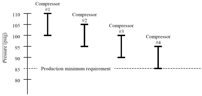
Figure 1: A cascaded pressure band arrangement may result in higher costs.
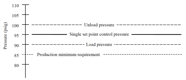
Figure 2: A compressor controller can keep the system at a lower pressure, reducing costs.
Remote Monitoring and Integration of System Components
Remote monitoring capabilities, with controllers, are very useful for plants. Several current generation controllers act as web servers. This allows plant operating personnel to connect the controller to the company’s internal intranet and monitor the compressed air system from any computer that has a web browser. Many have modems, as well, allowing monitoring from outside the facility.
Full integration of all components in the air system, not just the air compressors, is important. Filters, dryers and drains are available with contacts that allow remote alarms. Pick a controller that allows these components to be tied in together. Problems in one part of the system may be the result of a failure of one of these components. Problem solving is much easier if all of the information is readily available.
Data Requirements from a Controller
There should be a screen that provides an “at-a-glance” display of the current system status and current service and alarm messages. Using internet terminology, this would be the controller’s home page. It should display the operating status of each of the compressors and have links to the other displays on the server.
Look for controls that include a message history display. Message histories can act as the system’s black box that records events that might lead up to a sudden drop in pressure or the shutdown of some component in the system. Troubleshooting can be greatly enhanced by knowing exactly what was happening right up to the time an event took place.
There should be a display that allows the operators to look at all of the individual settings of all of the components in the system. This display should also show the control settings of the controller itself. If there is too much data to display on one screen, the controller should have links to the other screens that show additional system settings. It is much easier to point and click than to scroll down through 25 pages of information. Having these settings easily available allows current control schemes to be evaluated and changed if there have been changes in either the supply side or the demand side of the system. If production has increased, a process been moved to a different shift or a new compressor purchased, the control scheme should be reevaluated and possibly changed to optimize the efficiency of the compressed air system.
It is also important that a controller have the ability to provide data displayed as a graph
- Current system pressure and a selectable history – Showing the system pressure over time as a graph can be a great benefit when trying to optimize the supply side controls. Having real-time graphing, as well as the ability to pull up a day’s worth, or a week’s worth, or even a year’s worth of data as a graph makes it easy to identify how changes to either side of the system affect the pressure. Regular evaluation of this data can avoid production problems.
- Current air delivery of all of the compressors and each compressor, with a history -- As with the pressure, graphing the air delivery to the system can help operators optimize the supply side. If one compressor turns on only briefly and is then off for an extended period, the sequence of compressors might be changed to have a smaller compressor handle that particular load. Another possible solution might be to add storage to help the system ride through the event without having to turn on a compressor at all. Operators will only know this if they can look at historical data. Having the data in a graph form is the easiest way to review system performance.
- Current and historic specific power consumption – Again, being able to look at the specific power consumption of each compressor can allow operators to shuffle their sequences to have the most efficient machines running and the least efficient machines as standby.
Operating Cost Data and Outbound Calling
Since the software in the controller is monitoring all of the power and flow conditions, the next step is an analysis module that allows operators to track their actual costs associated with running the air system. With a screen that allows the input of power costs, including seasonal or daily changes in power costs, the controller can calculate how much money is spent to supply electricity to the system. Improvements to the system can be easily documented without having to have separate power metering to the compressors. Some controllers even allow operators to enter other maintenance costs and display the total cost of the air system in table and graph forms.
Another neat feature of some of the latest controllers is a call-out function. Equipped with a modem, they can call or fax trouble messages to either plant maintenance personnel on call or to the plant’s service provider. With a laptop computer and a phone line, the person notified can dial into the controller and take a look at the entire system. If it is the middle of the night, the information provided to the service technician can allow him/her to decide whether the problem requires immediate attention or can wait until morning. It also allows remote troubleshooting so the service provider can be certain to have the correct parts when they arrive on site.
Fifteen years ago, compressor controllers consisted of a box with a few remote pressure switches, a timer or two and some lights to indicate that compressors were supposed to be running. If operators wanted more information, they had to go to each compressor and write down the temperature and pressure. That was about all of the data they could gather. Today’s sophisticated integrated controllers actual manage the compressed air system. As with any good manager, they also provide reports and data to help others make correct decisions relating to the compressed air system.
Compressed Air Challenge Instructor Profile
Wayne Perry
Kaeser Corporation
511 Sigma Drive
Fredericksburg, VA 22408
540-898-5500 fax: 540-898-5520
wayne.perry@kaeser.com
Wayne Perry is a L1 Certified CAC Instructor and has 25 years' experience in all aspects of the compressed air business. He is currently Technical Director for Kaeser Compressors, Inc., the U.S. subsidiary of Kaeser Kompressoren GMBH.
Mr. Perry is Kaeser Compressor's representative to Compressed Air and Gas Institute (CAGI),a former chairman and current member of the Energy Awareness Committee, and Vice-Chairman of the Rotary Positive Section, which develops standards and performance reporting for rotary screw compressors.
As a UNIDO Compressed Air Expert and member of the International Team of Experts to the China Motor System Energy Conservation Program, Mr. Perry developed and taught a curriculum to prepare Chinese engineers to conduct compressed air system assessments, develop energy efficiency projects, and train factory personnel
To read more Technology articles, visit www.airbestpractices.com/technology/compressor-controls.


