The thread of previous columns focused on direct energy reduction as the savings. We presented calculations and the energy savings in a simple manner and only looked at the direct savings associated with electric power and compressed air reduction.
What we did not shine a light on is the additional and accompanying savings that inevitably come along with a well-applied and implemented operating system. These additional benefits include such as things as capital cost avoidance, reduced maintenance costs, safety improvements, increased productivity and product quality.
You may remember the article in the October 2018 issue of Compressed Air Best Practices® Magazine titled, “The Importance of System Pressure Control.” The article focused on a Midwestern manufacturing facility that produced a multitude of custom high-end performance touring and racing bicycles. This article features the same manufacturing facility and how improving its compressed air system, particularly in process grinding, allowed the plant to use the same compressed air system – while plant production increased by 30% to meet demand for its product.
Current Compressed Air System Overview
The plant’s current compressed air system operated as follows:
- Total average production compressed air flow: 1,500 hp or 1,243 input kW
- Total annual operating energy cost: \$411,085
- Total annual operating production hours: 6,240
Plant personnel had experienced ongoing problems with its process grinder performance due to unstable compressed air pressure. This created potential problems in terms of product quality. Grinders do not work properly without the proper pressure. Additionally, plant staff wanted to address these concerns, prior to a proposed 30% increase in production, and suggested raising the header pressure from the current operating pressure of 98 psig to 125 psig. The thought behind this was if the pressure from the header to the grinder process was dropping to 63 psig, then raising the pressure to the process would give the grinders enough pressure to work through higher peak production times.
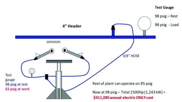
Figure 1. Current Grinding Process
As shown in Figure 1, the plant’s header system is set at 98 psig for the grinding process. When the process operated, however, the actual inlet pressure to the grinder fell to 63 psig from 98 psig. The header pressure did not fall but the pressure to the process fell significantly.
Metallic Surface Grinding: A Critical Function
Surface grinding is probably the most common of industrial grinding applications. The process is used for finishing and smoothing metallic or non-metallic materials for a polished and seamless look by removing surface impurities.
At the bicycle manufacturer, grinding is especially critical since the high-end and high-priced bicycles are used for racing rather than leisure activity. The pressure delivered to the grinders has a significant impact on the ability of a grinder operator to achieve the cosmetic and operational quality needed.
At the facility, a bicycle frame is brought to each grinding station where an experienced operator uses the grinder to smooth and polish the frame surface to remove welds where the frame is put together. Each operator is tasked with producing a seamless and uniform look to each bike frame’s aluminum alloy surface. After the frame is satisfactorily smooth it is sent to the powder coating area and then to assembly. Each grinder is rated at approximately 0.3 hp and uses roughly 33 cfm at each process.
Initial Proposal: Purchase a new 300 hp Air Compressor!
An initial solution proposed by an outside source suggested the plant consider purchasing and installing a new 300 hp air compressor. It was felt a new air compressor would not only cover the 30% production increase but would provide the 125 psig “needed” at the grinding processes to operate effectively - thus alleviating the low pressure issues.
While a new compressor would certainly help with the increase in production, it would come with an increase in capital used plus energy and maintenance costs. The addition of new compressed air supply components, i.e., a 300 hp air compressor, air treatment and new piping from the new equipment to the main distribution header, would include significant capital expense of not only the cost and installation of new equipment, but also the increase of pressure and total kW in the system.
Audit Finds Grinding Supplied by a 3/8” Air Hose Line
Given the significant costs involved, the plant brought in a third party to conduct an audit of the compressed air system and to assist in determining the best course of action. After reviewing all supply and demand-side equipment, the audit team along with plant operators, discovered the grinding processes were being supplied by a 3/8-inch air hose line, from the four-inch piping header.
This indicated the lines to the process air could only pass a limited amount of compressed air at 98 psig, so when the process wasn’t getting enough air, the system header couldn’t supply any more.
The audit team and plant staff ultimately determined the correct pressure needed at the grinding process was around 75 psig with the proposed modifications. It was suggested that each grinder process add a small 80-gallon compressed air storage vessel, pressure regulator and re-pipe the process to one-inch pipe in place of the 3/8-inch hose.
While the equipment supplier was very thorough in its evaluation and certainly addressed all the main plant concerns, what it missed was looking at all the Key Performance Indicators (KPI’s) in the entire system. Sometimes bigger picture items are often pushed to the forefront and addressed first - when often a look at the smaller, but no less important indicators such as minor piping changes and pressure regulation can, in some cases, save a larger and overall more expensive capital and variable cost.
This is illustrated in Table 1, which shows some very interesting and related calculations, including plant-provided data for the KPI’s in this system.
|
|
Current System |
Proposed System Option #1 (30% production increase) |
*Proposed System Option #2 (30% production increase) |
|
|
Max flow production |
New 300 hp compressor, new dryer, piping modifications and increased header pressure |
Pressure regulators, increase process storage and piping modifications |
|
Total system HP and input kW |
1,500hp / 1,243 kW |
1,800hp /1,492 kW |
1,400hp / 1,160 kW |
|
Current vs. proposed annual electric energy cost ($0.053/kWh) |
$411,085 |
$493,434 |
$383,635 |
|
Annual operating hours |
6,240 |
6,240 |
6,240 |
|
Annual production |
956 |
1,242 |
1,242 |
|
Current vs. proposed capital equipment costs |
$250,000 |
$650,000 |
$250,000 |
|
* The numbers used in this table were supplied by plant staff. This data and the calculations are proprietary and specific to the application. |
|||
Here’s a breakdown the capital and variable expenses for outlined options:
|
|
Option 1 |
Option 2 |
|
Total capital expense (equipment + installation) |
$650,000 |
$250,000 |
|
Five-year maintenance cost: |
$200,000 |
$100,000 |
|
Total estimated expenses: |
$850,000 |
$350,000 |
Examining the Options
As shown in Table 1, Option 1 would have provided the plant with an increase of compressed air at 1,800 hp and 1,492 input kW total. It would cost the plant \$650,000 to implement and an additional \$200,000 in maintenance costs over a five-year period and would cover the increase in production. This option would have cost the plant an additional \$82,349 annually in electric costs when compared to the baseline.
By comparison, Option 2 would provide the plant with the needed air for the production increase. This option would cost the plant \$250,000 to implement and an additional \$100,000 in maintenance costs over a five-year period. This option reduces the annual cost from the baseline \$27,450/year. Option 2 also would reduce the header pressure from 98 psig to 85 psig and saved 100 hp or 83 kW. The plant would also be able to regulate the air at each grinder process to 75 psig and add five additional grinder pedestals/stands.
Metal Fabrication and Machining Best Practices with Compressed Air Systems – Webinar RecordingDownload the slides and watch the recording of the FREE webcast presented by Andy Poplin to learn:
|
Meeting Increased Production Goals
After knowing the available options and associated costs, the plant moved forward with the compressed air system upgrade as described in Option 2. It included the following modifications to each grinding station:
- Removal of the 3/8-inch air feed hose.
- Added 1-inch compressed air supply piping from the header to each station.
- Increased effective compressed air storage and installed an 80-gallon storage vessel and pressure regulator at each station.
Implementation of the recommended solution gave the plant the ability to achieve its goals, including a 30% increase in production while using the current compressed air supply. It also allowed the plant to add five grinder stations/pedestals. Additionally, the entire system operates on 1,400 hp using the existing air compressors.
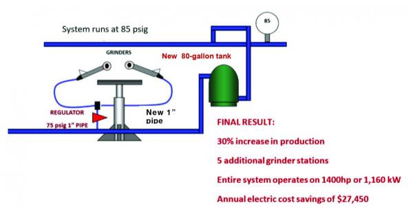
Figure 2. Corrected Grinding Process
Figure 2 illustrates the corrections to each grinding station as identified and implemented by plant personnel by the compressed air system audit. This was the “punch line” more production with reduced air demand by 500 cfm, or 100 hp less! It did not need a new air compressor!
With the implementation of Option 2 the plants annual electric cost total was \$383,635 rather than the proposed Option 1 of \$493,434, which represents an annual cost avoidance of \$109,799 per year and an operating energy reduction of \$27,450 per year
Final Thoughts
It’s important to note other recoverable compressed air costs should always be considered, e.g., air system maintenance, water costs, and equipment lifecycle. Usually, the electric cost of these is between 50-75 percent of the total “variable compressed air costs.” Productivity, maintenance costs and product quality are often more than 30% of the identified electric costs.
For this plant, Option 2 will always be ahead of the game when factoring in variable cost comparisons. In the real world, all costs whether fixed or variable, need to be accurately reported. Developing a clear lifecycle cost program is much more complicated than described in this article – but it demonstrates the moral to this story: Always follow the trail to the end conclusion and look at all the variables.
For more information contact Hank van Ormer, email: hank@airpowerusainc.com or call at 740-862-4112.
To read more End Use System Assessment articles, please visit www.airbestpractices.com/system-assessments/end-uses.


