By addressing inappropriate uses of compressed air and making changes to the compressed air production side of their compressed air system, a distiller of fine alcohol products reduced its energy consumption by 30%, saving \$16,600 per year in energy costs - with more potential savings possible.
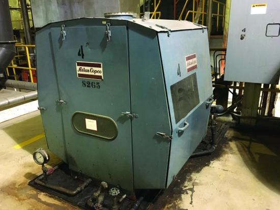
Figure 1: An air compressor has performed reliably for decades, but the aging unit needed to be replaced with a more modern, higher efficiency air compressor.
Background
The facility has a fermenting, distilling, storage and distribution operations onsite, all of which use various amounts of 100 psi compressed air. The compressed air contacts various products at different stages of processing in the facility, so there is the need to produce the cleanest possible compressed air to maintain quality and product safety.
The compressed air system consisted of three water-cooled, oil-free air compressors of various ages, running in load unload mode. Air compressor sizes were 110 kW, 90 kW, and 160 kW. The operation typically used the 110 kW unit for base load with the 90 kW air compressor starting for peak duty. The 160 kW unit, being very old, was used for back-up.
Drying is done using a heated blower style unit with dewpoint dependent switching to provide compressed air with - 40 oF pressure dewpoint. A refrigerated air dryer had been installed at one point for back-up duty, but was shut down due to maintenance issues.
The compressed air is directed throughout the plant through a system of steel piping. One medium sized 500-gallon storage receiver is located in the compressor room area as dry control storage, with various large receivers located out in the plant for peaking duty.
The compressed air is delivered to the multiple production areas through piping headers from which various branches are tapped to supply to each production operation. Installed data loggers showed minimal pressure loss across the piping system. Most of the pressure loss is across the drying and filtering system or across restrictor plates deliberately designed into the system.
System Baseline
The compressed air system electrical consumption was monitored as part of an extensive audit using amp loggers. Kilowatt readings using a hand held meter were taken for both the active air compressors to calibrate amps to power. System flow was recorded using the plant flow meter. Figure 2 shows the baseline during a two-week period.
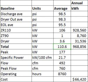
Figure 2: The distillery pays \$66,420 per year for electricity to power the compressed air system.
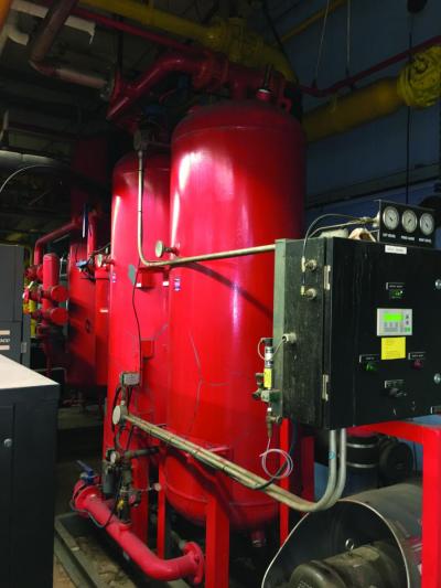
Figure 3: The heated blower style dryer maintains a - 40 oF pressure dewpoint.
The readings and observations during the measurement period showed the compressed air system was producing air at fair efficiency (21.7 kW/100 cfm). The assessment found problems with the air dryer cooling purge flow, higher than needed discharge pressure, some small leakage and drainage, and some possible inappropriate uses, were causing higher than desired operating costs and occasional pressure issues. The study found that significant improvements were possible.
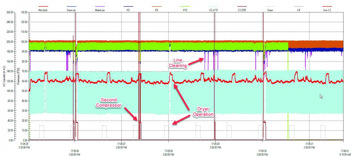
Figure 4: A typical baseline period shows the effects of dryer cooling purge. Click here to enlarge.
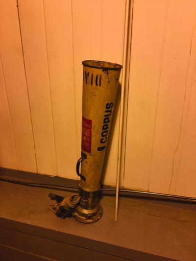
Figure 5: Devices like this compressed air-powered blowing horn were classed as possible inappropriate uses.
Inappropriate Compressed Air Uses
A survey of the demand side of the system was done including leakage. A total of 49 leakage points were found, estimated at 87 cfm. Various compressed air uses, which could be classed as inappropriate, were found including star seal blowing, bin vibrators, poorly adjusted dust collectors, compressed air vacuum, air horn blowers and fume blowing.
Shown in the red line of Figure 4 is the shape of the compressed airflow demand curve during production over a one-week period at the end of the data logging. The pressure profile shows good pressure regulation when only one air compressor is required. Dips in pressure can be seen on occasion when two air compressors are required. The profile shows a somewhat flat pattern during production activities, with higher peak flows just after the air dryer heating cycle. This is caused by the dryer cooling cycle where a flow of compressed air is directed into the desiccant to remove the remaining heat. If this is not done, a dewpoint spike will develop when the dryer stitches sides.
Additional peak flows are somewhat random, associated with clearing of alcohol lines after transfer of product. Compressed air is injected into stainless steel transfer lines to remove the remaining product before another ingredient is pumped.
These dryer-associated peaks, with coincident line cleaning, required two air compressors on occasion to run to support plant pressure. Although the second unit barely loads, it and the dryer heater, contribute additional cost to peak electrical demand.
Careful analysis of this profile showed that the air dryer was consuming higher than normal cooling purge, something that can easily be adjusted. It was thought that reduction of this would reduce the requirement for two air compressors, saving on peak demand. Savings could also be gained if leakage and inappropriate use could be reduced.
Potentially inappropriate end uses found were as follows:
- Air vacuum – A compressed air-powered drum vacuum was being used for cleanup purposes in an area where there is potential for explosion if spark-producing devices are used. The vacuum is created using a compressed air vortex, something that is safe, with few moving parts, but consuming about ten times the equivalent energy than a explosion-proof vacuum.
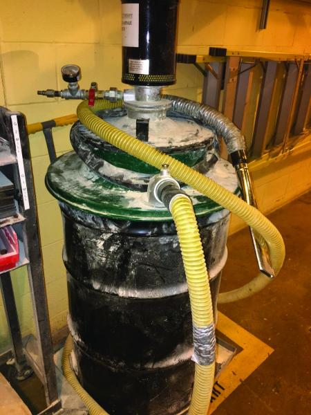
The distillery uses compressed air powered drum vacuums for cleanup, which is a inappropriate use of compressed air and not uncommon at many plants.
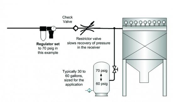
- Dust collectors - Reverse-pulse compressed air cleaners are installed on various dust collectors in the facility. These cleaners appeared to be controlled with the process and turned off when not required, which is excellent practice. The pulse duty when these units operate was undesirable, however, the pulse duration appears too long and the pulse frequency too high. As such, it wastes compressed air. Observation of the pressure gauge on each filter manifold revealed the problem This gauge should drop only about 10 psi on a quick valve operation for about one tenth of a second. The actual pulses are more like three quarters of a second, pulling the pressure down to about 35 to 45 psi each time with a pulse spacing of only six seconds. This problem is very common with these types of filters. A fix is to install a receiver at each filter with fill control to filter out the compressed air pulses as shown in Figure 7.
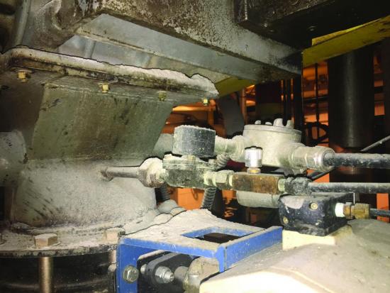
- Bin vibrators – Compressed air-powered vibrators were installed on the bottom of various bins to promote the flow of grain. These units consume six to 10 times the equivalent power of electric units.
Shown are bin vibrators used in the distillery’s process.
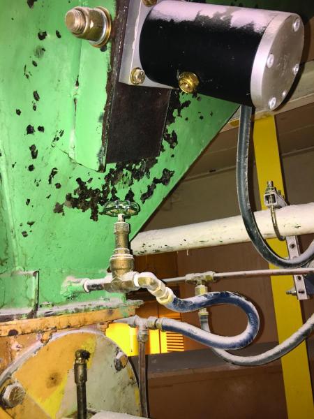
- Star seal blowing - Various blowing nozzles have been installed to clean the internals of star seals located on the top of some cookers. The constantly rotating seals meter the amount of ingredients going to the cooker, but because the input grain is dry, and the star seal is wet due to rising steam, the product sticks to the seal material, eventually creating clogs. These operations appear to be controlled with the process and therefore will shut off when not required. These blowers were measured and found to consume a peak of 126 cfm and average of 72 cfm.
Star seals are used on the cooker as shown to meter the amount of ingredients going to the vessel.
- Alcohol vapor blowing – A pipe with holes drilled in it has been installed over the area where the product barrels are unloaded. This appears to be an attempt to control fumes. This blowing was not in service the few times the Maturing area was visited but the operator there reported it is still used to provide “free air conditioning” on hot days. It appears that a fan-powered fume control system has been installed. As such, the compressed air powered ventilation can likely be removed.
- Air motor pumps – The distillery uses two small pumps driven by air motors. Air motors are used to ensure safety since explosions are possible if spark-producing devices are used. The use of air motors to do the job of electric pumps is energy intensive as air motor power costs about 10 times more than a direct drive electric motor.
Figure 6: Dust collector operation can be improved using this solution (Source: Compressed Air Challenge.)
Air Compressor Control Savings
The existing air compressors were running in load/unload mode with coordinated cascaded pressure bands. With this type of operation there are periods of time where the air compressor is unloaded running, consuming power, but producing no compressed air.
This area of inefficiency is identified in the red as shown in Figure 7, which is a profile of C3 air compressor amp logs sorted highest to lowest to form a histogram, also called a load duration chart. This area could be addressed by choosing an air compressor with a control mode that doesn’t have unloaded run time (like VSD operation).
Further to this, due to air compressor cycling, there is a period of time where the air compressor is in transition between loaded and unloaded, or reverse, indicated with the green highlight. This can be addressed by eliminating air compressor cycles using VSD mode.
And, in addition, there is extra power consumed by the air compressor if it runs at pressure higher than required by the plant as indicated with the yellow portion of Figure 7. This can be addressed by reducing the air compressor discharge pressure by adjustment of the pressure bands. Use of a VSD air compressor would allow a constant, lower plant pressure, rather than operating with a saw toothed waveform using load/unload control.
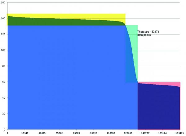
Figure 7: The load duration profile on the original air compressor power input shows areas of possible savings.
Conclusion
At the distiller, the following action items were taken:
- Installation of a new 132 kW oil-free VSD air compressor.
- Adjustments to the dryer cooling purge.
- Adjustments/repair of dust collectors.
- Repaired leakage, where economical. It’s estimated that 75% of repairs were completed.
Savings for these measures, based on air compressor histogram readings, are 257,000 kWh resulting in reduced electrical costs of \$16,600 for a 30% energy savings. The initial studies were made possible with the financial and resource support of the local power utility. The final project was also partially funding with incentives from the power utility. Further potential savings should be expected if this compressed air user follows up on additional leakage repair and addresses additional inappropriate uses of compressed air.
For more information contact Ron Marshall, Marshall Compressed Air Consulting, tel: 204-806-2085, email: ronm@mts.net
To read more System Assessment articles please visit www.airbestpractices.com/system-assessments.


