Introducction
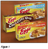
This article describes a compressed air retrofit project implemented at Kellogg’s Eggo (Figure 1) factory located in San Jose, California. Kellogg’s continues to realize both annual energy savings and quality improvements because of the upgrade. In addition, Kellogg’s received a substantial utility incentive from Pacific Gas and Electric Company, which was based on the achieved energy savings.
This Eggo factory is one of only two factories in the country currently producing the frozen breakfast treat. Three brothers, Tony, Sam, and Frank Dorsa invented Eggo waffles in the 1930 in San Jose, California. In 1953, the Dorsa brothers introduced frozen waffles – which do not require a waffle iron to prepare – to supermarkets throughout the United States. Eggo waffles get their name from their unique "eggy" batter. When the Dorsas first introduced the product, it was called "Froffles," a portmanteau of frozen waffles. However, people started referring to them as eggos due to their "eggy" taste. The name caught on and the brothers began using the moniker in marketing. Eventually the name became synonymous with the product and in 1955 the Dorsa brothers officially changed the name to the now famous "Eggo.” In the 1970s, as a means of diversification, the Kellogg Company purchased Eggo and Mrs. Smith's Pies. Their advertising slogan - "Leggo my Eggo" - is well known from their television commercials. http://en.wikipedia.org/wiki/Eggo
This program is funded by California utility customers and administered by PG&E under the auspices of the California Public Utilities Commission.*Pacific Gas and Electric (PG&E) funds the Ecos Air program to identify and implement compressed air projects that result in verified energy savings. As a third party administrator for PG&E’s compressed air efficiency incentive program, we at Ecos Air are totally committed to brand neutrality. While Ecos Air may utilize trade allies that also represent specific equipment or service companies, we do not endorse any product or vendor. “PG&E” refers to Pacific Gas and Electric Company, a subsidiary of PG&E Corporation. © 2011 Pacific Gas and Electric Company. All rights reserved. |
Baseline System
The Eggo factory uses compressed air for production, packaging, cooling, and clean-up processes. When approached by Ecos Air (see sidebar), Kellogg’s realized that in addition to decreasing the continued energy use of their compressed air system while simultaneously improving overall performance, there may also be an opportunity to receive a considerable monetary incentive from their utility, Pacific Gas and Electric (PG&E). The monetary incentive could offset the cost of the suggested energy reduction improvements.
The baseline system (Figure 2) was located on two supply pads (front and rear) with interconnected or looped piping at several locations throughout the factory. Each pad contained two (2) rotary screw air compressors with a total system capacity of 762 hp. In addition, there were two (2) refrigerated air dryers, two (2) line filter systems, two (2) small air receivers, and several timer condensate drains. The compressors were each set-up for modulation control before the upgrade was performed, which is typically the most common and inefficient control method in traditional multi-compressor systems.
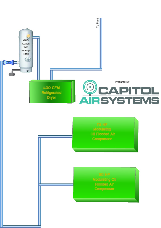
Existing Rear
Existing Front
Figure 2
Baseline Determination
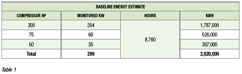
As a requirement of the utility incentive program, the auditor performed an analysis to determine the baseline energy usage of the system. This included collecting compressor power and system pressure data via data loggers and storage equipment. Afterward, the Ecos Air audit team used calculated flow and measured power to determine system overall efficiency by calculating CFM/kW. They extrapolated estimated/expected savings based on this demand profile for a full year. Graphs of the collected data (Figure 3) are shown below and tallied for the year (Table 1).
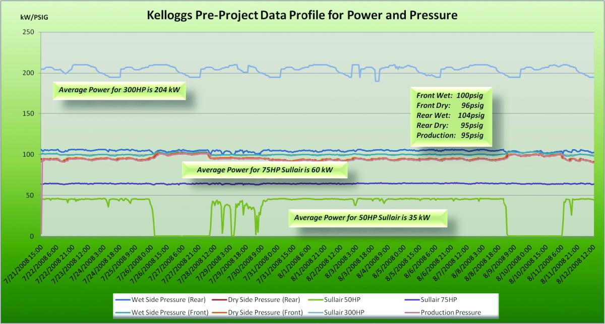
Figure 3. Click here to enlarge.
Issues with the System
The current compressed air system consists of two (2) 300 hp rotary screw air compressors, one (1) 75 hp rotary screw air compressor, one (1) 50 hp rotary screw air compressor, two (2) refrigerated air dryers, and two (2) line filter systems, two (2) small receivers, and several timer condensate drains.
• Local pressure switches and modulation regulators, typically the most common and inefficient control method, controlled each of the compressors.
• Minimal storage was available with approximately one (1) gallon per CFM.
• Existing piping was mostly galvanized which is dirty and had corroded over time.
• The system lacked pressure/flow control.
• Timed condensate drains were used.
• After implementing the project, and receiving the incentive, customer received the incentive, the Ecos Air audit team analyzed the system via ultrasonic leak detection to find and repair numerous leaks throughout the system.
The New System
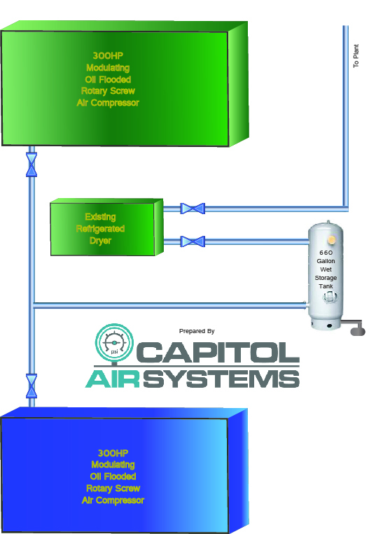
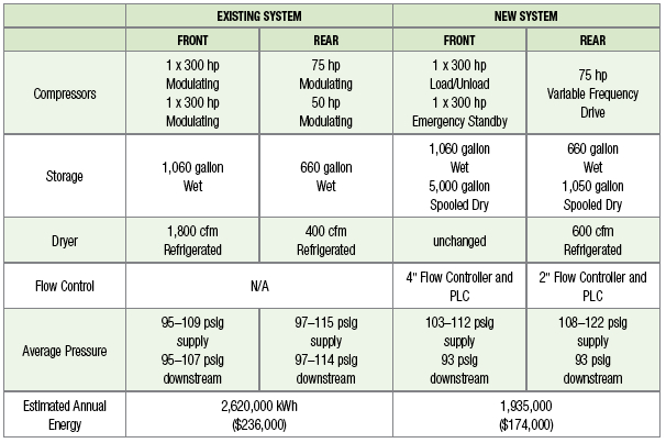
After the upgrade, they set one of the 300 hp compressors on the front pad for load/unload control to provide the base load and they set the other 300 hp compressor to emergency standby. A single 75 hp Sullivan-Palatek variable frequency drive compressor replaced both the 75 hp and 50 hp modulation controlled rotary screw compressors on the rear pad (Figure 4).
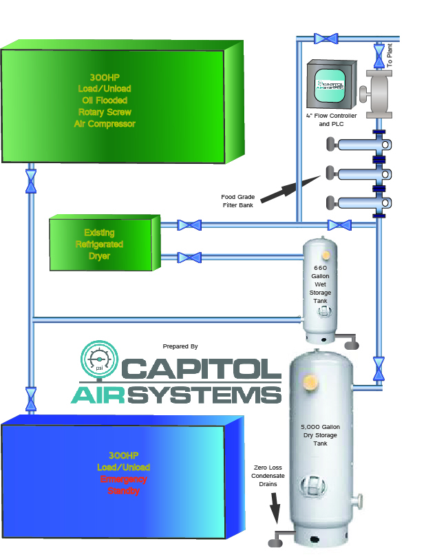
Front New
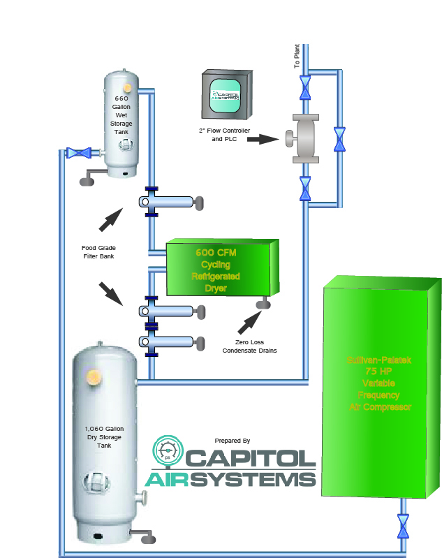
Back New
Figure 4
While the existing system did not have pressure/flow control, they upgraded the new system to include dual patented electronic pressure/flow control valves (Figure 5). On the rear pad, they installed supply system upgrades for the front pad included a 4” pressure/flow controller and a 2” pressure/flow controller. These controllers maintain downstream air pressure within +/- 1 psig. They selected this particular flow controller design for its resilience to inherent system contaminants like moisture and oil vapor after Kellogg’s determined that their plant operation is too critical to depend on traditionally problematic pneumatic pressure/flow controllers. For example, this controller is impervious to any compressed air contaminants while at the same time it does not have the negative hunting and malfunctioning issues that are inherent to most pneumatic pressure/flow control valves and occur when the performance of dryers or condensate drains begin to degrade. The electronic pressure/flow control valves maintain optimum efficiency in the event of other components in the system failing, thus preventing a domino effect of system component failure.
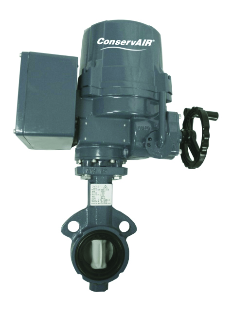
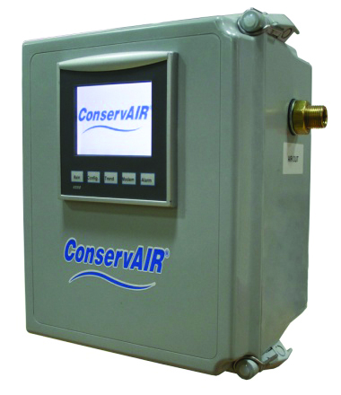
Figure 5
In order to improve the storage capability of the system, they modified the front pad to include one (1) spooled 5,000-gallon offline dry air receiver, while they added one (1) spooled 1,550-gallon offline dry air receiver to the rear pad. This brought the system storage capacity from approximately one (1) gallon per CFM to more than five (5) gallons per CFM. Next, and keeping in mind that the pressure drop of the filtration system is a large contributing factor to overall system efficiency, they upgraded the line filters to be oversized and include 3,000 SCFM of food grade filtration on the front pad and 600 SCFM food grade filtration on the rear pad. Throughout the supply pad, they installed new AIRnetTM anodized aluminum piping which does not corrode, is sanitary for food processing, and is easy to work with. This piping is also much safer and ergonomic for the system installation Field Service Engineers.
For condensate control, they replaced the timer drains on the front pad with five (5) zero air loss condensate drains and added one (1) condensate remediation pack. On the rear pad, they added one (1) 600 CFM cycling refrigerated air dryer and replaced the timer drains with six (6) zero air loss condensate drains and one (1) condensate remediation pack.
As previously mentioned, the Ecos Air audit team performed an ultrasonic leak detection audit after the incentivized upgrade was complete. Through this process, they identified and remediated approximately 324 SCFM of compressed air leakage through various fittings and machinery. In addition, the facility opted to install CDI flow meters downstream of each of the flow controllers in order to monitor their real compressed air usage in SCFM daily and weekly, allowing them to understand and control their current, variable, and future compressed air needs.
New System Monitoring Results
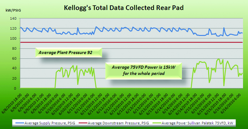
Figure 6
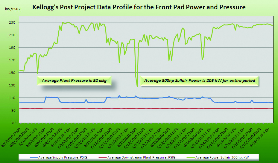
Figure 7
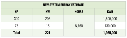
Table 2
Conclusion
The average air demands of the system were reduced from 1,347 SCFM to 1,296 SCFM due to the added receiver volume and a pressure/flow controller set point of 93psig. Another contributing factor to the reduced air demand was the replacement of 11 timer condensate drains with new zero air loss auto drains. In addition, part-load efficiency of the system was greatly enhanced due to a lower compressor pressure set point and the VFD control on the rear pad in lieu of modulating trim compressors that operated constantly. Now, the peak demand is met in the most efficient manner possible by the VFD trim compressor on the rear pad responding to the factory’s periodic peak demand needs.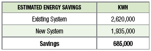
As a result of the above changes to Kellogg’s compressed air system, compressor output more closely matches system demand and continued energy costs have been reduced by approximately \$62,000 annually. In addition, Kellogg received a rebate of over \$71,000, which lowered the project cost by approximately 45%. Both the process and the project made Kellogg’s as a company much more aware of the importance of the compressed air system and its impact on their processes. The company is now more educated on the significance of inefficiencies and waste that can occur in compressed air systems.
For more information, please contact Patricia Boyd, Ecos Air, Technical Lead at 415-399-0661, email pboyd@ecosconsulting.com, www.ecosair.com, or Mike Mendoza mike@capitolair.net.


