When the 18th Century Italian physicist Giovanni Venturi discovered when air is forced through a conical nozzle its velocity increases as the pressure decreases, neither he nor anyone could conceive it would ultimately spawn one of the most used and most highly controversial products in the industry today- the Venturi vacuum generator (aka, ejector).
- Many end users, through lack of information, do not fully understand the benefits of this product and most importantly it’s limitations. To further confuse the issue, various manufacturers call them different names, i.e. pump, ejectors, vacuum transducer pump, etc. The most accepted general category name is Venturi Vacuum Generator, which describes exactly what it does.
- To some it is the greatest thing since sliced bread. To others it is a constant waste of air. Continuous product development by industry leaders has made these products, when properly applied, not only convenient and responsive but often a very energy efficient selection.
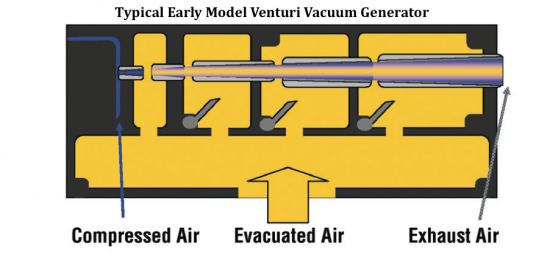
How it Works
In its simplest form, the single- stage Venturi generator flows air through the conical Venturi orifice. As the conical orifice opens in size, the pressure falls and the velocity increases. The intensity is such that a vacuum (lower pressure than ambient air pressure) is formed and air to be evacuated from the process is pulled into the flowing airstream and blown out.
Venturi Vacuum Generator Advantages
- No moving parts
- Vacuum is on and off immediately with the air supply
- Low Cost
- Quick to repair or replace
- Can be located very close to process reducing the amount of evacuation air and offering faster cycle times
Venturi Vacuum Generator Disadvantages / Opportunities
- Use more plant air to pull a higher degree of vacuum
- Standard units use compressed air whenever turned on
- 100 psig class compressed air is more energy expensive to produce than vacuum
- Performance can be sensitive to compressed air supply pressure
Basic Operating & Design Considerations to Take Advantage of the Positive Features and Minimize the Negative
The Venturi vacuum generator uses compressed air whenever it is on; therefore minimizing the ON time is PARAMOUNT. Deliver only the vacuum you need and then shut off the “Compressed Air Supply Line” to the generator. Do not shut off the Vacuum Line to the process because the compressed air will usually continue to flow.
Venturi Vacuum Generators should generally be located as close as possible or of the actual process:
- An effective Venturi Generator offers great flexibility in a decentralized system when well controlled.
- With a decentralized system and Venturi generators are mounted close to the suction cups or on the cup itself. The air use is minimized by reducing the volume to be evacuated, eliminating excess hoses, bends, fittings, valves, filters, etc.
- When a proper system design strategy is implemented, it will take advantage of the ability of the Venturi vacuum generator located near the process to react quickly and pull the required vacuum quickly, then shut off the air supply whenever possible.
- Utilizing the current state- of- the- art Venturi vacuum generators- low pressure inlet compressed air, auto shut off of the air supply (and vacuum), reduced size and better cup choices to use the lowest possible vacuum level- will almost always deliver efficient vacuum with regard to compressed air use.
Developmental Changes Introduce Multi-Stage Generators
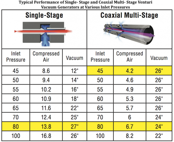
Multi- stage vacuum generators were developed to improve this efficiency for many applications. The multi- stage units use a series of ejectors and nozzles that allow compressed air to expand in controlled stages. This usually improves the ratio of compressed air consumption to vacuum flow to a level of about 1:3 or better. Multi- stage units are also significantly quieter and can develop vacuum at lower pressure. This performance will reduce compressed air flow required under the same conditions and/ or decrease reaction time and increase productivity. It is important to not operate multi- stage units at other than their rated inlet pressure or the valve timing will be negatively affected. Early models were large and somewhat cumbersome and often could not be mounted near the cups.
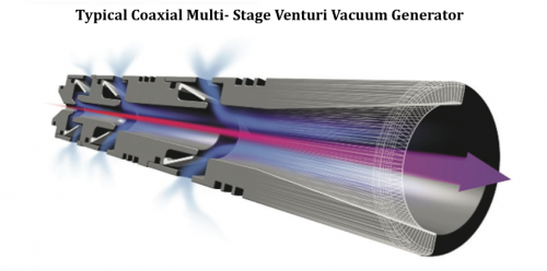
Coaxial Multi- Stage Venturi Vacuum Generator
Coaxial units are multi- stage vacuum generator with the multi- stage valves installed around a coaxially covered tube, this significantly streamlines the flow profile through the generator. Basic design allows the coaxial cartridge to meet and deliver many different flow and pressure requirements. In many cases the coaxial cartridge inside the generator body can be exchanged with another to allow the same hardware to meet varying conditions with optimum energy efficiency at relatively low cost. Development and production of the coaxial multi- stage Venturi vacuum generator brought more to the game than just a more efficient air- driven vacuum pump. The very characteristics of its design miniaturized the product while greatly improving performance and lowering maintenance and repair, which also led to dramatic changes in Venturi vacuum system design and configuration to further reduce compressed air usage limited only by imagination.
New Energy Efficient Venturi Vacuum Generator System Accessories and System Design Opportunities for Reduced Energy Impact
- Use of Low Pressure Inlet Compressed Air
Recently developed coaxial multi- stage Venturi Vacuum Generators can be properly applied to lower inlet compressed air pressure resulting in less compressed air use to generate the same basic air removal to reach a similar vacuum level. Coaxial pumps high and low pressure cartridges are often interchangeable within a body.
- The Use of Lower Vacuum Levels Means Faster Evacuation Time and Lower Energy (Compressed Air Use)
The majority of evacuation time is from 12” Hg and deeper vacuum. Therefore, use a lower vacuum level with larger or more appropriate cups whenever possible is to be considered. Proper cup selection is very critical to optimize the operating costs and productivity, and new vacuum cup technology continues to expand the opportunities.
For example a 40mm diameter vacuum cup with 27” of Hg vacuum level will lift a nominal 5.5lbs. A 75mm diameter vacuum cup at 18”of Hg vacuum level will lift a nominal 22lbs. The increase in the level of vacuum from 18” Hg to 27” Hg will be up to 10 times less energy efficient.
Establishing “End of Tool Technology”
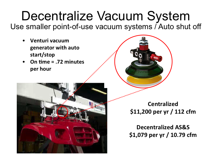
The miniaturization of these very effective even lighter and smaller generators some now with 3D printer manufacturing, this has allowed further and faster use of the “End of Tool Technology.” This allows a process to go from a centralized to decentralized application with the Venturi Generator mounted directly on the vacuum cup itself. Instead of evacuating all the air in the feed lines from the centrally mounted vacuum generator, the only evacuation air volume is the amount below the cup. Combine this with built- in auto air shut off and the required compressed air flow is often reduced to almost a negligible “puff.”
This allows machinery system designers to take more advantage of end-of-tool evacuation when space and cycle times allow. Compressed air flow is still there to offset any leakage and not drop the piece.
Case Study
On a recent auto plant audit we were able to measure the compressed air usage on a centralized system with the following equipment- (2) Larger Central Vacuum Generators operating at 87psig with 3 cups per generator. The air consumption was 112scfm with 40 cycles per minute which would be about \$11,200/ year at \$0.06 kwh/ 8,000 hours/ year.
Converting the six cups to “End of Tool Technology” with vacuum a generator mounted on each cup with auto shut off lowered this to 10.79scfm for 40 cycles per minute; at a cost of \$1,079/ year at the same conditions. Therefore, a projected annual savings of \$10,121/ year for this one process.
Other New Accessories to Improve the System When Applicable
Suction Cups with Built- In Evacuation Air Shut Off is a product available with very high potential energy impact is the newly developed cup connectors with a built- in valve that only opens when the cup sets on the piece and vacuum is needed. These valves close when there is no piece to pick up.
In the case where multiple cups are on the machine and various sizes and shapes of pieces are to be picked up, any unused cups will not pull open ambient air into the evacuation airstream. Thus optimizing the compressed air use in the process.
Constant open flow into the evacuation airstream will increase the compressed air on- time required for the working cups to reach the target vacuum level. In some cases it may require reduction in cycle time to avoid product drops.
Vacuum Regulators in Place of Compressed Air Regulators
These vacuum regulators directly control the actual vacuum level instead of the inlet pressure to indirectly control the vacuum level. Tests have shown this will minimize the “on time” much more effectively.
Summary
Throughout the past fifty years, the air- driven Venturi vacuum became more and more popular as manufacturers of production machinery found their size, feasibility, and inherent fast response time allowed design flexibility and most importantly, line speed increase. This is especially true during the 1980’s and 1990’s as automation surged in search of productivity improvements.
Unfortunately, little attention was paid to the operating energy cost of these products, which utilize compressed air- a plant’s most expensive utility.
Other than the multi- stage Venturi vacuum generator, which was and still is a most significant development, very little true innovation has implemented with the basic technology. Most development centered on and around industry issues such as control. The biggest missing piece has been product knowledge and training from the production machine manufacturers to plant engineering and maintenance personnel.
We hope you’ve found this interesting and look forward to your comments! Contact Hank van Ormer, email: hankvanormer@aol.com, tel: 614.580.2711
To read similar System Assessment End Use articles visit www.airbestpractices.com/system-assessments/end-uses.
Read all the articles of this series:
Missed Demand-Side Opportunities Part 1 - Flow Restrictions from Pipe Headers
Missed Demand-Side Opportunities Part 2 - Integrating Multiple Air Compressor Controls
Missed Demand-Side Opportunities Part 3 - Controlling Open Blowing with Compressed Air
Missed Demand-Side Opportunities Part 6 - Look to AODD Pumps To Lower Compressed Air Demand
Missed - Demand-Side Opportunities Part 7 - The Importance of System Pressure Control


