In this ongoing column, we share insights into technologies that offer the opportunity to affordably and easily lower compressed air use and generate energy savings – all while achieving relatively quick payback. But finding these technologies on the production floor isn’t always easy or straightforward. In fact, there are many times when a technological solution is far less than obvious. Such is the case with cooling of control enclosures, which represent a significant area for high-energy savings with little upfront investment. Here is some out-of-the-box thinking… check that… inside-the-box thinking… for optimizing control of enclosure cooling and coming out ahead.
Compressed Air and Control Enclosure Cooling Go Together
You may be asking what does control enclosure cooling have to do with compressed air, but they do in fact go together.
One of the most effective methods of control enclosure cooling, particularly in very harsh conditions, is with compressed air-driven products. However, when applied without any sort of regulation, this can be the least economical type of enclosure cooling. And remember: Control enclosure cooling, when needed, is important since it can extend the life of critical electronic equipment and reduce maintenance and downtime.
When utilizing a control enclosure, most equipment designers select the enclosure size and resultant cooling area with regard to normal internal heat rejection, basing this selection on a maximum internal temperature target of 90˚F. Basic industrial equipment is usually designed to operate in 100˚F or lower ambient, unless otherwise stated.
Enclosure coolers often come into the operating plant already installed on production machinery, such as presses, formers, packaging units, etc. Plant personnel often are not aware of the selection parameters since the cooler is perceived as “part of the package” from the OEM. However, it’s easy to overlook the fact that many applications in ambient areas with temperatures over 90˚F for sustained periods may well require auxiliary enclosure cooling, particularly if the equipment is older.
The key question is whether the facility needs enclosure cooling. Yet the answer dictates the need to take step back and ask important questions:
- What is the internal temperature when operating under all appropriate conditions? The enclosure itself is effectively a heat sink; it will transfer inside-generated heat to a cooler surrounding area, or it will transfer heat from a hot surrounding area into the enclosure. On the other hand, if the surrounding area is air-conditioned with a normal 70˚F temperature, the heat sink effect of the enclosure may be all the cooling needed.
- Is the enclosure is located in a very hot area? If it is, determine whether it’s practical to move the control enclosure to a cooler location.
- Is the enclosure using compressed air to hold inside positive pressure to prevent the intake of outside contaminants? If yes, there are enclosure-cooling devices, such as air-driven Vortex units, that will cool and vent the internal enclosure while it is completely sealed.
- Is there room around the enclosure and sufficient airflow to deliver stable air temperature year round?
If the operation determines it needs auxiliary control enclosure cooling after factoring in these considerations, plant personnel can determine what type and what size unit best fits the plant’s needs with minimum operating energy and maintenance cost.
Evaluating Commercial Control Enclosure Coolers
Commercial control enclosure cooling comes in six basic types: Fan (blowing filtered ambient air); compressed air open blow (at ambient temperature); refrigeration (Freon-based); refrigeration (heat tube); thermoelectric refrigeration (400-1,500 Btu/hr. range); and compressed air driven vortex tube refrigeration.
Here are insights into available choices to aid in decision-making:
Fan with Ambient Air: Internally Mounted, Drawing in Filtered Air
If the ambient air temperature surrounding the enclosure is more than 90˚F, cooling the inside of the enclosure below 90˚F is unrealistic with this technology. This type of cooling depends on “exchanging the air” and requires a certain amount of cooler air coming in and hotter air going out to handle the Btu/hr. load. It is limited in application since it will only work with “cooler” ambient air. Although very low energy users, they work best when operating conditions will allow proper performance and the conditions are stable.
Compressed Air Blowing Directly into the Enclosure
Assuming compressed air being blown is also at ambient temperature, it will not deliver much better performance than the fan-driven ambient air cooler option except for increased density. Overall, it is very expensive to produce compressed air. In addition, unless this air is dry and filtered, it can carry oil, water, and contaminants into the electronic controls. We do not recommend this practice.
Freon-based Refrigeration Units
Freon-based refrigeration units can lower the ambient air temperature about 15˚F to 16˚F each pass. For more cooling drop, the refrigeration action is cumulative as long as there is enough capacity. This usually limits their usage to ambient temperatures no higher than about 125˚F for optimum performance.
The refrigeration usually mounts on the side of the enclosure and continues to cool the same air inside the enclosure over and over until the desired internal temperature is reached. The units usually run at a constant speed, but when there is enough refrigeration capacity, these units may be controlled to shut off with a temperature switch. In practice, they often run most of the time – particularly if a hot gas bypass valve is controlling them. There is no electrical energy savings in the hot gas bypass valve (HGBV) control model.
Heat Pipe or Heat Tube Refrigeration
A heat pipe consists of a sealed metal tube whose inner surfaces contain capillary wicking material. Inside the container is a liquid (alcohol or similar) under its own pressure that enters the pores of the capillary material, wetting all internal surfaces. Applying heat at any point along the surface of the heat pipes causes the liquid at that point to boil and enter a vapor state. When that happens, the gas picks up the latent heat of vaporization. The gas then has a higher pressure, and moves inside the sealed tube to a colder location where it condenses. Thus, the latent heat of vaporization moves heat from the input to the output end of the pipe. This process takes place at high speed.
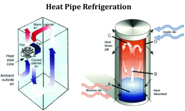
The core materials selected for use in the heat tube enclosure coolers are typically copper tubing and aluminum fins. The fans are normally axial type and designed to be an easily changed replacement part.
The lowest electrical energy cost for refrigerated control enclosure cooler is often the heat pipe. Air-cooled units can only cool to almost ambient temperature. When the ambient temperature around the box is higher than the desired inside temperature, they will not work.
When ambient temperatures are too high to allow air-to-air heat refrigeration, water-cooled versions are available. Like the air-to-air units, the air-to-water units are flush mounted and have no exposed fans or fins to protect. They offer below ambient cooling and even lower electrical energy use per Btu/hr. than air-to-air units. They require available cooling water inside the sealing tubes at 50-60 psig and about 1-2 gpm. These use most sources of process or cooling water, while not significantly raising the process water temperature. These units perform very well and no water enters the enclosure to harm any electronics. Air-cooled units are limited to about 3,500 Btu/hr. heat loads. Water- cooled units go up to about 60,000 Btu/hr.
Thermoelectric Refrigeration
An older technology now emerging into the commercial industrial control enclosure cooling market is “thermoelectric refrigeration.” It was first developed and applied to internal cooling of computers and other electronic components. Thermoelectric plates utilize the Peltier cooling design. As current to the plate is reduced, the cooling effect is reduced. The control system modulates the amount of current to maintain a target temperature.
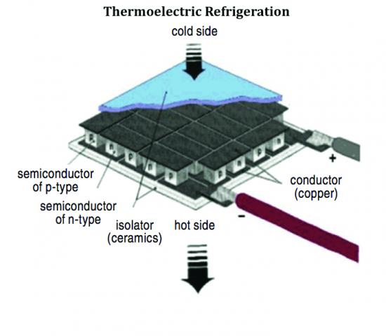
The energy cost to operate a thermoelectric refrigeration control enclosure cooler is from 50% to 80% less than Freon refrigeration units. This technology does not always have the capability to develop the higher temperature differential of some other solutions, particularly vortex tube cooling.
Thermoelectric refrigeration is usually available in units from 1,500 to 3,000 Btu/hr. cooling in a single unit. It will handle many of today’s smaller enclosure cooling jobs in the industrial environment. It will cool below ambient air temperature, but is limited to a cooling temperature differential of (10˚F to 20˚F) below ambient.
Refrigeration – Vortex Tube Cooling
Vortex tubes generate chilled air without the use of refrigerant or any moving parts. As compressed air flows through the tube and vortex generator, hot air blows out of one end and cold air out of the other. The vortex flow generator is an interchangeable, stationary part. It regulates the volume of compressed air. Everything else being equal, as the inlet pressure rises, the cold air temperature drops (within performance limits). A compressed air temperature drop of up to 90˚F is available at about 90psig inlet pressure in many models.
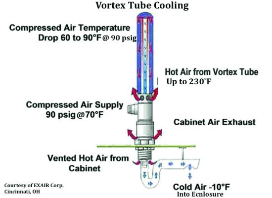
Lower inlet air pressure or backpressure on the cold end will reduce pressure ratios across the tube and raise the cooling air temperature. There is usually a relief valve in the vortex tube cooler assembly venting the enclosure air, allowing backpressure to not build up, and exchange hot air for cold air. Since well-applied vortex tubes cool quickly and have no moving parts, they can shut on and off as often as required to save airflow. Vortex tube coolers should always be controlled by a thermostat sensing the inside enclosure air and an electric solenoid to shut the air on and off with the signal.
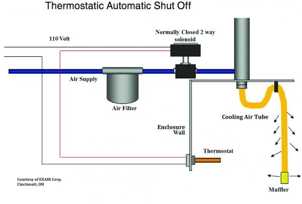
Vortex Tube Refrigeration coolers are least affected by high ambient temperature with regard to performance and operating life. When applied in such areas as “wash-down”; high dust; and corrosive elements, etc. they require a sealed enclosure and a positive internal pressure. Most manufacturers offer a built in bypass in the control solenoid. This allows a small amount of compressed air to flow into the enclosure when the Vortex Tube Cooler is off.
Summary
- Filtered fan air and open blowing of system compressed air are often not the proper selection for ensuring optimal performance and operating cost.
- The lowest energy cost refrigeration – when it can be applied correctly – is the HEAT PIPE-air-cooled units that can only cool to almost ambient temperature. When the ambient temperature around the box is higher than the desired inside temperature, the application will call for water-cooled units, which are also very energy efficient but do require a source of cooling water.
- Thermoelectric refrigeration units are still relatively small in cooling capacity and limited to about a maximum of 20˚F temperature reduction below ambient.
- Vortex tube coolers are the most versatile coolers due to the fact that they can hardly be misapplied as far as cooling. They can definitely be misapplied as far as inefficiency and wasting compressed air – your most expensive utility. Always install vortex tube coolers with properly selected automatic temperature controls to maintain energy efficiency.
- Vortex tube coolers can generate significant temperature drop. The higher the pressure, the lower the temperature within the design limits.
- A vortex tube cooler works well in any refrigeration application. With little to no maintenance and infinite life compared to Freon refrigeration, it is always a safe selection.
These innocuous control enclosure coolers, attached like a growth on production machinery, will often offer a significant opportunity for energy reduction and probable productivity improvement when optimized.
Case Study: Automotive Plant
At the plant, a review showed that a compressed air system comprised of twenty 6,000 Btu/hr. Freon-type Refrigeration Control Enclosure coolers were not working and were scheduled for replacement. Instead, the plant chose to replace them with twenty 6,000 Btu/hr. air-to-air HEAT PIPE units.
Cost savings
- The heat pipe units used .140kw for a total of 2.8kw. The annual energy cost for the units totaled \$1,472.00 (2.5kw x .06kwh x 8760hrs).
- The Freon Refrigerated units that were replaced were rated at an average 2.0kw each for a total of 40kw. The annual energy cost was \$21,024 (40kw x .06kwh x 8760hrs).
- Total annual savings = \$19,552.
Payback
- The installation cost for twenty heat pipe units was approximately \$16,000, resulting in a simple payback in less than 10 months.
Case Study: Aluminum Rolling/ Mill
This Aluminum Mill had 5000 Btu/hr. Freon Refrigeration coolers mounted above the furnaces. These were failing several times a year due to the high operating ambient temperature of 140˚F to 150˚F. The mill replaced the units with Vortex Tube Refrigerated Coolers rated at 80+ scfm demand. The new enclosures for the units, which deliver automatic temperature control, were well insulated.
Cost savings
The Vortex Tube Refrigerated Coolers operated for two years without with an annual average flow of 25.8 scfm (about 4.75kw). As such, it saved \$2,386 in annual electric energy cost (4.75kw x 0.6 x 8760 hrs).
Conclusion
Demand-side opportunities can appear elusive but they often exist in places that require a closer look. This doesn’t make “one technology better than the other.” The key is to understand and apply the proper technology to the application.
We hope you’ve found this interesting and look forward to your comments! Contact Hank van Ormer, email: hankvanormer@aol.com, tel: 614.580.2711.
To read similar System Assessment End Use articles visit www.airbestpractices.com/system-assessments/end-uses.
Read all the articles of this series:
Missed Demand-Side Opportunities Part 1 - Flow Restrictions from Pipe Headers
Missed Demand-Side Opportunities Part 2 - Integrating Multiple Air Compressor Controls
Missed Demand-Side Opportunities Part 3 - Controlling Open Blowing with Compressed Air
Missed Demand-Side Opportunities Part 6 - Look to AODD Pumps To Lower Compressed Air Demand
Missed - Demand-Side Opportunities Part 7 - The Importance of System Pressure Control


