A significant manufacturing operation, in the U.S. Midwest, had successfully deployed a compressed air leak management program. This on-going leak management program, along with tuning the air compressor control system, had delivered energy savings and a more reliable compressed air system.
Plant maintenance and facilities management then asked our firm to identify more ways to reduce compressed air demand, while they continued on with the leak management program.
Our compressed air audit found the following further compressed air demand reduction opportunities. The objective of this article is to provide examples of how plants can further reduce compressed air demand – after having implemented a successful, on-going compressed air leak management program.
All projected savings in this audit reflect an air compressor control system able to translate demand reduction into energy savings. The system operates 8,760 hours per year and the local electric rate was $0.07 per kWh. Average system pressure is 90 psig. Please note, due to article space limitations, this is an excerpt from a larger audit, and should be used only as an idea generator.
Summary of Demand Reduction Projects
| DEMAND-SIDE Project and Savings |
CFM |
Peak kW | kWh |
$ Savings |
Project Costs |
| Summary of Demand Repair identified leaks and continue leak management program |
40 cfm |
6.0 |
52,303 |
$3,700 |
$1,500 |
| Install thermal control on vortex controls in control room |
18 cfm |
2.7 |
23,536 |
$1,700 |
$500 |
| Install venturi nozzle on Grit Blast remove and plug unnecessary blows |
278 cfm |
66.9 |
363,505 |
25,500 |
$2,000 |
|
Remove compressed air blows for Pickling; install two 10-hp low pressure blowers |
170 cfm |
14.4 |
125,928 |
$15,600 |
$25,000 |
| Install automatic no-air-loss condensate drain |
33 cfm |
4.9 |
43,150 |
$3,000 |
$5,500 |
|
TOTAL |
539 cfm |
94.9 kW |
608,422 |
$49,500 per year |
$54,500 |
Project #1: Compressed Air Leak Survey
Prior to our site visit, plant personnel have aggressively found and repaired a significant number of compressed air leaks. As a result, we found a very small number. Plant personnel have acquired an ultrasonic leak detector able to help them detect, photograph, quantify and record leaks.
Most plants can benefit from an ongoing air leak management program, like the one this plant has deployed. Generally speaking, the most effective programs are those that involve the production supervisors and operators working in concert with the maintenance personnel.
A partial survey of compressed air leaks was conducted at the plant and 11 leaks were identified, quantified, tagged, and logged. Potential savings totaled 41 cfm for the 11 leaks that were identified.
| Number of leaks | 11 leaks |
| Air reduction | 40 cfm |
| Recoverable savings from air flow reduction | $91.53/cfm yr |
| Annual electric cost savings with proposed project | $3,661/year |
| Unit cost of leak repairs ($25 materials per leak and $75 labor per leak) | $135 |
| Overall cost of leak repairs | $1,500 |
|
No. |
Location |
Description |
Est Size |
Est Cfm |
Comments |
|---|---|---|---|---|---|
| 1 |
R-1 |
Push pull fitting | Small |
1 |
|
| 2 |
R-1 |
Filter | Small |
2 |
|
| 3 |
R-1 |
2 air switches | Medium |
5 |
Sonic air tank |
| 4 |
R-1 |
Regulator | Small |
3 |
Sonic air tank |
| 5 |
R-1 |
Cylinder | Medium |
5 |
Sonic air tank |
| 6 |
R-1 |
Purge regulator | Medium |
5 |
Dryer in east compressor room |
| 7 |
R-1 |
Regulator | Medium |
5 |
Crane |
| 8 |
R-1 |
Top of filter | Medium |
5 |
2 high kickoff table |
| 9 |
R-16 |
Hose reel fitting | Small |
2 |
Dept. 300 |
| 10 |
R-16 |
Hose reel fitting | Medium |
5 |
Dept. 400 |
| 11 |
R-45 |
Regulator | Small |
3 |
Reclaim |
| TOTAL SAVING (cfm) |
40 |
||||
Project #2: Install Automatic No-Air-Loss Condensate Drains
These condensate drains come in a number of varieties, including ones that receive the signal to open from a condensate high level and the signal to close from a condensate low level. These drains waste no compressed air and are the best selection from a power cost standpoint. Their reliability is usually many times greater than the level operated mechanical drains.
Ensure that automatic condensate drains are set up to work effectively. Some guidelines include making sure all drains:
- Are not tied together to a common header
- Can be checked easily for operation
- Are properly “vented” to atmosphere, if necessary
- Are sized, piped “to” and “from” with the full capability to handle anticipated highest humidity weather loads
- Include a bypass bleed on the feed pipe
- Can be easily checked to see if they are passing condensate
Connect each drainage point (after-cooler, pre-filter, dryer, after-filter, receivers, and all risers) separately to individual drains to collect and direct the condensate to a proper handling point. Be sure maintenance personnel can effectively and visually monitor the drain’s action.
| Air flow (cfm) savings per drain (each) | 3 cfm/yr |
| Total of number of drains |
11 |
| Total compressed air saved |
33 cfm |
| Recoverable energy savings from air flow reduction |
$91.53/cfm yr |
| Total annual energy savings (33 cfm x $91.53/cfm year) |
$3,020/yr |
| Cost per drain (materials and installation) |
$500 each |
| Cost of project (11 drains x $55 per drain) |
$5,500 |
Project #3: Open Blows / Blow-off Air
Many plants have “open blows” where turbulent compressed air blasts straight out of the pipe or tube in order to dry a product or “blow off” unwanted materials from a product. This not only wastes huge amounts of compressed air, but also violates OSHA noise and dead ended pressure requirements.
One savings approach is to use an air amplifier, which requires less compressed air. Air amplifiers use “venturi” action to pull in significant amounts of ambient air and mixing it directly into the air stream, which amplifies the amount of air available at the point of use. Air amplifiers have amplification ratios up to 25:1. Using 10 cfm of compressed air can supply up to 250 cfm of blow-off air to the process and generate a savings of a 15 cfm compressed air per 1/4-inch blow off. Savings may be available using 1/8-inch lines, but the cost effectiveness will not be as great.
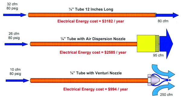
In many cases, an appropriately selected and applied venturi amplifier will deliver lower net energy cost blow-off air than blower-generated blow-off air. The capital cost for the amplifiers is relatively low.
Tips for Using Air Control Nozzles
-
Always select the lowest flow nozzles that will achieve the desired result to maximize air consumption savings and noise reduction.
-
Install a pressure regulator and gauge in the air line before the air control nozzles and regulate pressure down to the absolute minimum necessary to achieve the desired result. Lower pressures improve safety, reduce noise, and could save hundreds of dollars a year in electricity operating costs.
-
To minimize noise, increase the distance between the target surface and the nozzle, if possible. Remember that noise is caused by air impacting on the target work piece, particularly edges or holes.
-
Install adjustable ball joints in the supply line, if required, with air control nozzles to provide simple, accurate adjustment of nozzle orientation.
-
Do not aim the nozzle straight at the target for cleaning applications. Angle the nozzle 15º to 45º to ensure that the contaminants are removed from the product surface.
-
Most nozzles, in an appropriate material, can be used with CO2, Nitrogen, steam, or other compatible gases for special heating or cooling applications.
-
To create an air curtain, nozzles do not always need to be positioned as closely as on an air knife. Nozzles can be up to 12” (30 cm) apart depending on the application.
-
You can aim the nozzle to “wipe” sideways across a moving target at a comparatively shallow angle for many blow-off applications. This can reduce the number of nozzles needed.
-
Angle the nozzle manifold like a snowplow above a moving conveyor so that the contaminants are forced off the belt, rather than back.
-
Proper filtration of compressed air is important for efficient nozzle performance. Be sure to use a filter/separator to remove excess oils and water just prior to your nozzle application.
| Estimated high pressure air used currently |
585 cfm |
| Estimated high pressure air used saved installation of venturi nozzles |
277 cfm |
| Estimated compressed air saved with venturi nozzles |
278 cfm |
| Recoverable savings from air flow cfm reduction |
$91.53 cfm/yr |
| Total electrical energy cost recovery by installing venturi nozzles to reduce blow by |
$25,445/yr |
| Cost of nozzles and installation (62 nozzles x $32 per nozzle) |
$2,000 |
Venturi Inducer Nozzles in Place of Open Blow
| Location | Qty |
Type/ Size |
Utilization % |
Current Application |
Proposed Application |
Net Savings (cfm) |
||||
|---|---|---|---|---|---|---|---|---|---|---|
| Air Flow Capacity (cfm) |
Net Usage (cfm) |
Recommended Venturi Nozzle |
Air Flow Capacity |
Net Usage (cfm) |
||||||
| 1 | Grit blast | 65 | Lechler |
62 |
14 |
555 |
48008 |
7 |
277 |
278 |
|
TOTAL |
555 |
277 |
278 |
|||||||
Misapplied Compressed Air
High-pressure compressed air (90-120 psig) being used for low-pressure applications (7-60 psig), is not an efficient use of energy. A close review of the plant’s system should be made and measurements taken to identify whether there are any potential energy savings from using an alternate source of low-pressure air for specific applications in the production area. Typical misapplications include aeration and spraying.
In this plant, there are three dip tanks being aerated. Two of them are rinse tanks, being aerated using 90 psig compressed air, and the acid tank is being aerated by a 25 horsepower roots blower at 7 psig. This blower is oversized and is being throttled back.
We estimate approximately 85 cfm is being used in each tank. All tank liquids were “boiling” very well, with a lot of turbulence in the tanks.
Our recommendation is to replace the 90 psig compressed air aeration with the 7 psig low pressure blower system already being used in the acid tank and adding a 10 horsepower low pressure blower able to produce 96 cfm at 10 psig with a maximum working pressure of 17 psig.
| Estimated air flow in current low pressure application at 7 psig | 170 cfm |
| Recoverable savings from air flow reduction | $91.53/cfm yr |
| Annual electric cost in current application | $15,560/year |
| Electric demand of new unit | 11 kW |
| Annual hours of operation for current equipment | 8,760 hours/year |
| Annual electric cost in proposed application (at 170 cfm and 10 psig) | $6,745/year |
| Net annual electric savings | $9,665/yr |
| Total cost to purchase and install a new blower | $25,000 |
Conclusion
Plant maintenance and facilities personnel should implement on-going compressed air leak management programs. Once up and running, there are many other ways to reduce compressed air demand – beyond leaks.
For more information on APenergy visit apenergy.com or call 740.862.4112.
To read similar Compressed Air System Assessment articles, visit https://www.airbestpractices.com/system-assessments.
For expert presentations, visit our Webinar Archive Section dedicated to Air Compressor Technology at https://www.airbestpractices.com/magazine/webinars.


