It is an amazing fact that some compressed air systems run so very efficiently, yet others are so wasteful. In this day and age with all the awareness out there on the Internet, in addition to numerous training sessions offered, it is a source of amazement that some systems are still needlessly wasting thousands of dollars in annual electricity and maintenance costs.
In the words of author Charles Dickens, “It was the best of times, it was the worst of times, it was the age of wisdom, it was the age of foolishness.…”.
That phrase best describes what we experience as compressed air consultants and our examination of two compressed air systems in two different cites. One operates at a mail sorting facility in one city with very poor efficiency, while another at a separate mail sorting facility is of a much better design. The difference in annual operating costs is striking. One system has air compressors twice the size of the other, yet most surprisingly the biggest system uses much less energy.
Check-valve Protected Air Compressors Create Trouble
The compressed air system at the mail sorting facility has been in service since the 90’s. Two older 50-horsepower (hp) air-cooled fixed-speed lubricated air compressors are housed in the equipment room of the facility. The air compressors duty cycle alternates between one another on a set schedule. A 240-gallon wet storage receiver is used to help with air compressor control, with the air flowing through the receiver to a non-cycling refrigerated air dryer and system filters before finally being passed to the plant.
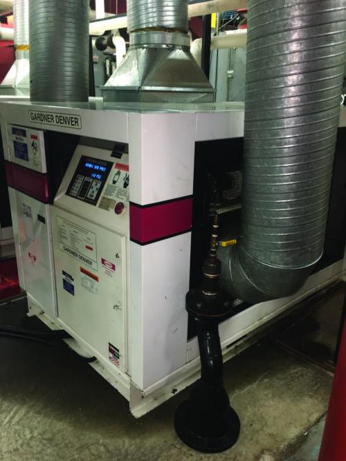
Installed in a hot boiler room, this modulating rotary screw air compressor consumed excessive power and required air conditioning to keep it running.
Each air compressor is check-valve protected, a feature typically seen in older installations where previous air compressors were reciprocating rotary screw air compressors. Check valves were often installed on reciprocating units so system pressure would not cause problems when starting the air compressors. Since modern screw-type machines have check valves built into them, the presence of these extra units actually causes problems in coordinating air compressor control, since it is difficult for local air compressor controls to “see” the actual system pressure through the check valves. Given this situation, the second air compressor at the facility had to be manually stopped making it unavailable to start should the primary air compressor shut down, reducing reliability.
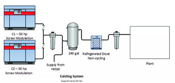
Shown in the compressed air system arrangement at the facility with two 50-hp air compressors.
Assessment Shows High Power Consumption
At the start of the compressed air system assessment the customer was asked if they knew how much compressed air they were using. They had no idea because there were no flow measuring instruments. Therefore, a flow meter was purchased for the job and left in place for future use.
Since the system control storage was very small, and the air compressor controls were poor, the air compressors ran in a combination of modulation and load/unload. Power monitors were placed on the air compressors, as well as various points in the system to measure pressure and on the flow meter. Data analysis showed the following results:
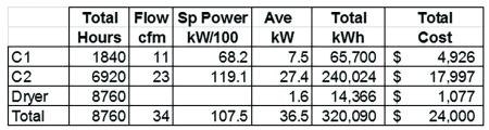
Table 1: Total annual cost to operate the compressed air system is \$24,000.
The data showed this system was very lightly loaded compared to the full capacity of the air compressors, with compressed air flows at about an average of 34 cfm. The power consumption was considerably higher than expected, however, averaging about 36.5 kW. The calculated specific power, including the dryer was 107 kW per 100 cfm, an extremely poor value for a system. Expected specific power for smaller systems should be in the range of 21 to 23 kW per 100 cfm. This shows a very high potential for savings on the production side of the compressed air system.

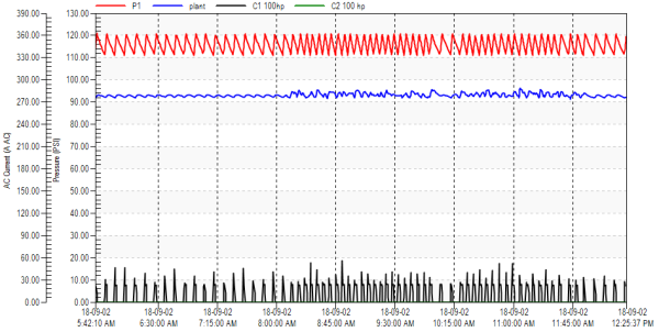
Shown is a typical 24-hour pressure/power/flow profile. Even though both air compressors are the same make and model, the one used most consumes more power (yellow line) under similar loading conditions than the other (lower red line). Click here to enlarge.
This system had operating problems because it was installed in a hot boiler room where the air-cooled air compressors would often overheat. This high temperature overloaded the air dryer and allowed moisture to form in downstream piping. The problem had become so troublesome that air conditioned air was directed into the air compressor coolers, reducing air compressor operating temperatures, but adding significant cost to the compressed air system.
One additional problem with this system was bypass piping. The bypass lines for system filters and the air dryer were run under the devices forming low spots in the air compressor room header. Since the compressed air flowing past the bypass lines is 100% saturated, having low spots allowed moisture to form in the bypass loops. In fact, the bypass loops were completely full of water when tested. Every time the filter and dryer bypass loops were opened to perform system maintenance a slug of water would flow into the system, contaminating downstream devices.
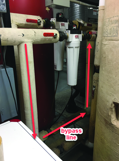
A poor bypass installation allowed water to collect in bypass pipes.
Similar Operation, Much Less Power Consumption
The second compressed air system, located in a different city, was used in the very same way on almost identical facility loads. In mail sorting facilities the compressed air demanded by the sorting machines has greatly reduced as technology changed to high-speed sorters, requiring fewer humans and much less compressed air.
This second system consisted of two 100 hp air-cooled Variable Speed Drive (VSD) lubricated air compressors installed in a separate well-ventilated room of the facility. The air compressors duty alternates between one or the other on a set schedule. A 1,550-gallon wet dry storage receiver was installed to help with the air compressor control, with the air first flowing through a cycling thermal mass refrigerated air dryer, and through low differential mist eliminator system filters, as well as a pressure flow controller set to 90 psi, before finally being passed to the plant. Each air compressor is placed in lead position by changing the pressure settings every week. One unit carries the load, while the other provides back-up protection should the lead air compressor fail.
A full compressed air audit was not done on this site, so no flow meter was installed, but flows can be calculated based on air compressor duty. Since the plant flows are low, these air compressors operate start/stop below minimum speed.
The data showed these 480 cfm-rated air compressors produce air only 20% of the time and the remaining time they sit in standby duty. It was very unsettling walking into a clean cool and quiet air compressor room where all the air compressors have automatically turned off in a facility that operates twenty four hours a day, seven days a week. Average power was measured at 6.4 kW while producing 21 cfm of compressed air. This system specific power worked out to 30 kW per cfm including the air dryer, which is not optimum, but it consumes considerably less power than the system designed in the same manner as the first facility. Total power consumption worked to a projected 56,000 kWh per year costing about \$2,800 per year in electrical charges. This system, despite having a capacity twice as large as the older facility, consumes five times less power.
Addressing the Issue of Oversized Air Compressors
This newer system is greatly oversized, and air compressor experts will be horrified to see the system operating well below minimum speed, a less desirable operating regime for VSD air compressors.
It is because this system is oversized that specific power is much higher than optimum range of between 21 and 23 kW per 100 cfm. But, it beats the alternative of having rapidly cycling undersized fixed speed air compressors operating mostly unloaded. Manufacturers advise VSD operation under minimum speed should be avoided because in this range there is not enough heat generated to boil off the water from the air compressor lubricant that forms because of condensation during air compression. In hot humid environments this can be a problem. Luckily, this facility is cool and dry, and very good maintenance is performed on the air compressors. The system has been operating this way for over ten years with no major problems. Due to the large storage capacity, and wider than normal start/stop pressure band, the air compressors run for a significant period of time when they start, allowing internal temperatures to build up to near normal.
The facility’s VSD units are shown operating in start/stop mode, which reduces power consumption. Click here to enlarge.
As is very often the case a customer does not know what exact size their air compressor should be when they build a facility. In this case, due to the size of the building, and based on historical data the system was estimated at needing 100 hp of capacity. But changes in technology in the end-use equipment greatly reduced the actual requirement.
When this system was purchased and installed, the local power utility got involved and persuaded the customer to purchase VSD air compressors, as well as an efficient dryer, and a very large storage and a pressure regulating device to lower plant pressure. The utility was not successful in persuading the customer to reduce the size of the equipment, but it is because this very efficient equipment was installed that the final operating costs were so low. In ten years each compressor has only operated an average of about 1,300 hours per year, minimizing the maintenance costs.
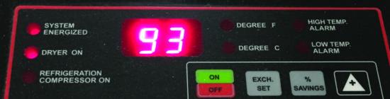
The display panel of the cycling air dryer reports an average energy savings of 93%.
Energy Savings of 87 Percent Possible
The first compressed air system has some significant problems and high potential for future savings. Recommendations to improve the system included the need to right-size the air compressors reduce discharge pressure closer to flow control valve setting, and reduce leaks. Specific improvement measures were as follows:
- Install a new VSD lubricated air compressor with cycling dryer (and 660 gallons storage).
- Reduce air compressor discharge pressure.
- Remove (or do not install) air compressor check valves.
- Improve air compressor ventilation.
- Reconfigure filter and dryer bypass lines.
- Use remote sensing on air compressor pressure sensing.
- Install airless condensate drains on air compressors, dryers, filters, receivers.
- Implement or install air compressor efficiency monitoring.
- Repair 10 cfm in leaks.
Projected savings for these measures would save 277,000 kWh and reduce electrical costs by 87% The potential savings for these measures should be expected to bring the system specific power down to normal levels. However, since the air compressor is only consuming \$2,800 in annual costs even the projected 45% savings for these measures would only gain a financial saving of about \$1,600 per year.
Mapping Out a Path
The comparison of these two compressed air systems shows the extreme difference in operating costs of a well designed system compared to a poorly operating system. The choice of air compressor size, system storage, dryer and filter type, and operating pressures can cause a big difference in the end result. Will you have the best of times, or the worst of times with your compressed air experience? It’s up to you to map out that path. Or to borrow from Dickens again, you might be able to say to yourself “It is a far, far better thing that I do, than I have ever done ...”.
For more information contact Ron Marshall, Marshall Compressed Air Consulting, tel: 204-806-2085, email: ronm@mts.net.
To read more System Assessment articles please visit www.airbestpractices.com/system-assessments.


