Introduction
There are three essential ways to transmit power in heavy industry today: Mechanical, Electrical and Fluid Power. Under the umbrella of fluid power, you have hydraulics and pneumatics as the two fundamental technologies. Both use a form of fluid – hydraulics as a liquid and pneumatics as a gas, to transmit power from one location to another.
It is extremely important to keep the liquid or the gas clean as it flows through the fluid conductors and works its way from the reservoir in hydraulics and the receiver tank in pneumatics, through the directional valves and on to the business end of the system or the actuator. Chevron states: “Particle contamination is the number ONE cause of lubricant-related failure in equipment. An estimated 82% of wear is particle-induced, with abrasion wear accounting for two thirds of the figure. It’s no secret, hydraulic fluid contamination is the leading causes of hydraulic system failures.”
Facilities spend an enormous amount of money on oil analysis programs and work very diligently for proper filtration placement to make sure their hydraulic systems and mechanical devices, such as gear reducers, run trouble-free for years. But what about pneumatics? No one pays much attention to the quality of their air because compressed air is free, right? It doesn’t spill on the ground so even the reliability, environmental and safety departments don’t pay much attention to it. However, the energy costs to run the compressors in a facility “can” be the second highest cost behind the raw materials to make the product!
Pneumatics
Most pneumatic circuits run at low power, usually around 2 to 3 horsepower. Two primary advantages of using pneumatics over hydraulics are 1) low initial cost and 2) design simplicity.
Because pneumatic systems have much lower operating pressures than hydraulics, the components can be made of inexpensive materials and often mass-produced with processes such as injection molding and/or die-casting. Typically, engineers look at this “first cost” and might not consider operating costs can be sometimes five to ten times higher due to the cost of the horsepower to compress the air.
Also, when a gas is compressed, the temperature increases and holds water vapor. When the gas moves down the lines it cools, causing the air to become saturated with water and eventually leads to moisture somewhere downstream. So you could say heat indirectly contributes to poor air quality on the downstream components.
Why Do Pneumatic Components Fail?
The Effects of Poor Air Quality on Demand Side Components
[As we move through this article I am assuming that all precautions have been taken on the supply side of your compressed air system. The downstream components I will discuss are meant as a precautionary measure, and not as the first line of defense!]
So how does poor air quality affect the downstream or demand side components, such as directional valves, flow control valves, pressure control valves, and linear or rotary actuators?
Typically, there are three primary component “killers” in your compressed air system: moisture, particulates and dry (unlubricated) air. “Wait, does my air need to be wet or dry – make up your mind.” Hang in there and I will explain! Contamination is defined as any foreign substance in the fluid or gas impeding performance.
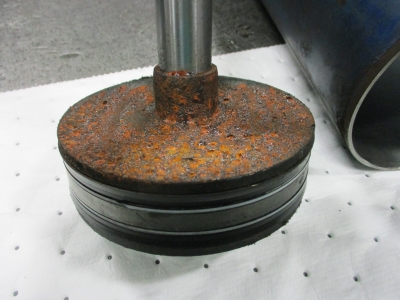
Figure 1: Severe Corrosion. (Image courtesy of Motion Industries).
Moisture
Figure 1 shows severe corrosion on a double-acting pneumatic cylinder piston. This cylinder is in operation in a pulp and paper mill, whose paper machine has very high humidity on the wet end.
This corrosion, caused by moisture over time, will become dislodged and get pushed through the other components. This in turn will cause a multitude of problems, such as sticking spools in the directional control valves, plugged orifices in pressure control, and flow control valves causing malfunctions. As the name implies, these downstream components “control” the operation of the actuator and tell it what to do.
Again, this moisture can be generated from several places: the heat of compression at the compressor, ingression from the production lines, and fluid conductors going from inside of the facility to outside and back to the inside. Keep in mind we are concentrating on the downstream side of the system – NOT the supply side – so hopefully in the design phase, someone thought about a dryer at the compressor’s discharge.
What Do We Do About Moisture?
In-line coalescing filters, in-line desiccant dryers, and water separators are just several products commercially available to remove this water from the demand side of the system.
Coalescing Filters
Coalescing filters should always flow from the inside of the filter element to the outside of the filter element. This allows for the oil and water droplets to collect on the fibers of the filter element and meet at crossover points and become larger and larger droplets (the process of coalescing) as they travel downward and outward to the base of the filter element. The large droplets drop off the base of the filter element into the sump area of the filter housing and ultimately into an automatic float drain where the liquids are drained out of the system.
Desiccant Filters
Point-of-use desiccant filters dry compressed air through adsorption represents a purely physical process where water vapor (adsorbate) is bound to the drying medium (adsorbent) through binding forces of molecular adhesion. Adsorbents are solids in spherical and granular form, and are permeated by an array of pores. The water vapor is deposited onto the internal and external surface of the adsorption medium, without the formation of chemical compounds taking place; therefore the adsorption medium does not have to be replenished, but only periodically regenerated.
Water Separators
Oily condensate from the compressed air system enters the oil/water separator under pressure, and is allowed to expand in the specially designed centrifugal inlet chamber. During a six-stage process, the water and oil are separated, allowing the cleaned water to be safely discharged to the foul sewer through the outlet, while the drained oil is collected in an external oil container where it can be disposed of according to legal requirements.
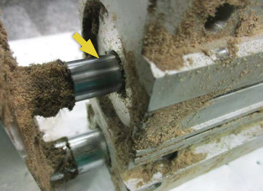
Figure 2: Particulate Ingression Point. (Image courtesy of Motion Industries).
Particles
Just like moisture, particles can come from many places in a complete system. They can be ingressed through dirty filters on the inlet of the compressor, they can be ingressed from the product during normal production, and they can be self-generated from components wearing internally. Figure 2 shows a typical ingression point on a double-acting pneumatic cylinder due to poor maintenance practices.
These particles flow thorough the fluid conductors and if the facility does not have properly placed filtration, the particles will become lodged in the piston seals and rod gland seals and act like emery cloth on the rods and barrels, causing severe scoring, leaks and premature failures.
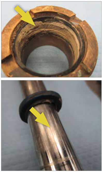
Figure 3: Particles lodged in the rod gland seal and matching scoring on the rod. (Image courtesy of Motion Industries).
Figure 3 shows heavy scoring on the rod, causing the rod gland seal to leak due to the particles lodged in the soft parts.
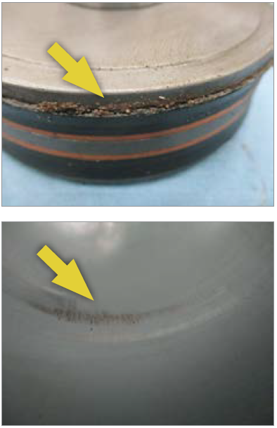
Figure 4: Particles lodged in the piston seals and matching scoring marks in the Barrel. (Image courtesy of Motion Industries).
Figure 4 shows the same scoring on the inside of the cylinder barrel due to the particles lodged in the soft parts. Remember, due to the low operating pressure of pneumatics, these cylinder barrels are typically made of aluminum and can be easily damaged.
What Do We Do About These Particles?
There are several commercially available products to remove these particles from the demand side of the system. Air filters are designed to remove airborne solid contaminants, pipe scale, rust, pipe dope, etc. These may plug small orifices or cause excessive wear and premature failure of pneumatic components.
Dry (Unlubricated) Air
The only reason I mentioned this type of failure is because many manufacturers of the newer products, such as pneumatic cylinders, send these components out pre-lubricated on the soft parts inside the cylinder and is lubricated for the life of the unit. However, the previously mentioned moisture has a tendency to wash this lubrication out, meaning the soft parts are now moving dynamically exposed to the dry air and no lubrication. This exposure will cause the seal to dry out, crack and prematurely fail. These cracks in the seal allow air to bypass internally, and cause the cylinder to slow down and eventually just stop. Due to the low cost of these components, the cylinder is typically replaced with no regard to the root cause of the failure. One day I heard a statement: “50-cent failure, 50-cent analysis as to why it failed.”
Demand Side Component Placement
When setting your key performance indicators to measure the performance of your demand side components, it is important to know a few important things: 1) the operating pressure vs. the required operating pressure, 2) the rate of flow vs. the required rate of flow, and 3) the direction of flow vs. the required direction of flow.
Figure 5 shows an example of typical component placement to measure the KPIs for proper operation. From the drop line you have an in-line flow meter, a particle and or water removal filter, a pressure regulator, a lubricator, a directional valve and the cylinder.
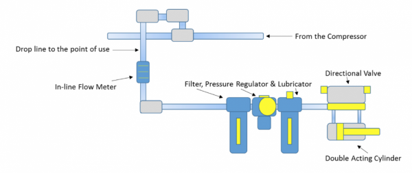
Figure 5: Demand Side Component Placement. (Image courtesy of Motion Industries).
Setting and Measuring Your KPIs
Having the KPIs listed and posted at the point of use is important for predictive maintenance checks and logical troubleshooting.
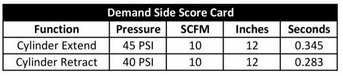
Figure 6: KPI Score Card. (Image courtesy of Motion Industries
Figure 6 shows an example of the KPIs charted for easy access by the operator, the PdM technician or the system troubleshooter.
Conclusion
The demand side of a compressed air system is often the most neglected part of the machine set in an entire facility, yet according to the Department of Energy just 10 quarter-inch leaks can cost as much as \$39,967 in energy costs to compress the air that is being wasted. Spending just a little time to set your KPIs and installing some inexpensive components on the system’s downstream side can extend the life of your components and reduce unwanted production interruptions.
To read similar articles on Pneumatics, please visit www.airbestpractices.com/technology/pneumatics.


