Introduction
Most compressed air applications have varying demand based on the process for which the compressed air is being used. There are many choices of compressor technology and types of controls that can be used for variable demands. Some examples are rotary screw compressors with inlet valve control: variable speed drives: load/unload control; or centrifugal compressors with variable inlet guide vanes. However, in many cases, the efficiency of the overall compression process can be reduced significantly during lower flow demands, leading to more power per unit of air flow being delivered. It is very important to evaluate different available options and see how a plant can run most efficiently.
Centrifugal compressors can be a very good choice for certain applications where the variable demand can be met within the turndown range of centrifugal compressors. Centrifugal compressors are well known for their reliability, efficiency and air quality. Let us now understand the centrifugal technology and its use in variable demand with a varying load application.
Centrifugal Compression
Centrifugal technology uses dynamic compression, where air is drawn between the blades of a rapidly rotating impeller and accelerates to high velocity. The air is then discharged through a diffuser, where the kinetic energy is transformed into static pressure. Most dynamic compressors are turbo compressors designed for larger volume flow rates. The flow and pressure in dynamic compressors is controlled by an inlet device (Inlet Guide Vane or butterfly valve) and an unloading valve. The turndown in dynamic compressors can be 30 to 35% or more depending on the inlet ambient conditions. Turndown, also known as throttle range, is the flow range of a centrifugal compressor as compared to full load capacity. For example, a compressor with a full load design point of 1000 cfm and 30% turndown, can modulate capacity to 700 cfm prior to unloading. Centrifugal compressors have variable flow rates and variable pressure characteristics.
Many centrifugal compressors use Inlet Guide Vanes (IGVs) to control the suction flow based on the demand requirement. IGVs redirect the air flow by pre-whirling to the suction, hence, an IGV is more efficient (9% better than a standard butterfly valve at partial loads) and offers more turndown.
Since you are not reducing the speeds to achieve required turndown in centrifugal compressors, a standard motor can be used. Special motor and frequency drives are not necessary.
The following are two possible control methods that can be used with centrifugal compressors: auto dual control or constant pressure control. Depending upon the application, you can choose which control is more suitable.
Auto-Dual Control (See Fig. 1)
- The standard regulation is achieved by means of inlet guide vanes and controller.
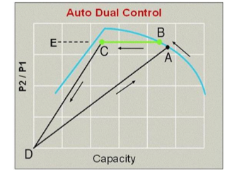 Figure 1
 - The compressor discharge pressure set point (B) will be set at the desired level and the throttle or IGVs will modulate the compressor inlet to maintain constant discharge pressure over the control (B®C) range.
- At the surge control point (C), the IGVs stop closing, allowing the discharge pressure to rise to the unload set point. At this moment, the compressor will unload (IGVs close and unloading valve fully opens).
- The compressor remains in the unloaded condition until the system pressure declines below the preset load set point (A), the compressor resumes load at full flow, and the cycle is repeated.
- Re-loading time may be variable depending on capacitance.
If the compressor does not need to reload within a fixed time period, the unit will stop automatically. The controller will automatically re-start and load in anticipation, when the system pressure falls to the load set point (A).
Constant Pressure Control (See Fig. 2)
- This control method uses the inlet guide vanes (IGVs), unloading valve (ULV), and controller.
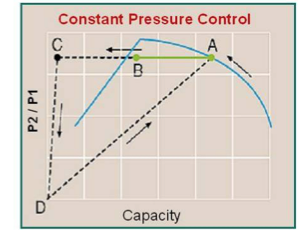 Figure 2
 - The compressor discharge pressure set point will be set at the desired level and the IGVs will modulate the compressor inlet to maintain constant discharge pressure over the control (A®B) range.
- At the surge control point (B), the position of the IGV is maintained fixed, the unloading valve starts to modulate open, and the excess compressed air is exhausted to atmosphere.
- In this way, a constant discharge pressure is maintained over the full operating range of the compressor (A-C).
Some controls can also provide for a maximum unloading valve (ULV) position to be programmed. This allows the plant to minimize inefficient operation during periods of low demand by limiting blow-off operation to a point between (B®C).
The constant pressure control system is designed to continuously control the air output while keeping the net pressure fluctuations to a minimum.
Example:
Plant has 8000 cfm peak demand, 5800 cfm average demand, and 3000 cfm minimum demand during weekends at operating pressure of 100 psig.
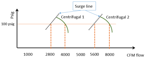
As shown in above figure, we have selected two 4,000 cfm centrifugal compressors to meet the peak demand. During peak demand both compressors will run at full load. When the flow demand is reduced to the average demand of 5800 cfm, the two centrifugal compressors will close the inlet guide valve and run in its turndown range without exhausting any compressed air to atmosphere.
During the weekend, when the demand reaches to minimum flow, one centrifugal compressor will stop and only one compressor will run in its turndown range. With this combination, the centrifugal compressors will work most efficiently and save a plant significant energy.
The area between 4000 and 5600 cfm of flow is called a control gap. In this situation, it has been made clear that the customer will not normally require maximum air flows in this range. However, should this change, blow off would be required by the second compressor in order to not exceed the air flow requirements. Alternatively, an additional unit or units could be utilized. This would eliminate the need for blow off and fill the control gap. In order for such a system to properly function, a master controller/sequencer would be required.
Conclusion
This is just one example to demonstrate increase plant efficiency and energy savings. When a plant's demand pattern has been determined, the proper selection of centrifugal compressors with a master controller can be made. Proper equipment selection will ensure a plant's compressed air system is reliable and efficient.
|
The Compressed Air and Gas Institute (CAGI) is the united voice of the compressed air industry, serving as the unbiased authority on technical, educational, promotional, and other matters that affect compressed air and gas equipment suppliers and their customers. CAGI educational resources include e-learning coursework, selection guides, videos, and the Compressed Air & Gas Handbook. The Centrifugal Compressor Section consists of the following member companies:
For more information, visit the CAGI web site at www.cagi.org. |
To read similar articles on Air Compressor Technology, visit www.airbestpractices.com/technology.


