Introduction
If you’ve been in the compressed air business long enough, you’ve heard the following contradictory statements about the same project – usually given after start-up and a difficult customer call:
Service manager: “I sent Joe out there, and he started up the system. Everything was running perfectly when he left! I can deploy another technician (a different one – Joe is out) right away. If you have a technical question, ask the engineering department.”
Engineering: “All our XYZ systems were designed as ordered. I have never heard of that problem before! If the customer needs to be taken care of, talk to the sales manager.”
Sales manager: “Talk to the service manager!”
I have been involved in many of these “do-loops” in my OEM experience as Engineering Manager, and have always seen them as fruitless to solve the real problem. Most often, the root problem lies within the specification and start-up/testing phases.
What is the “testing” that needs to be done on site? It is part of “commissioning”, abbreviated as “CX”. Don’t cobble-together a system and expect the start-up technician to work miracles. Execute commissioning in steps, flushing out the bugs as you go.
Background
In Part 1, I made the case that full system commissioning is needed whenever a compressed air system is significantly modified. And I suggested the following definition of commissioning:
“Compressed air system commissioning is the process for measuring, testing, adjusting, and documenting that the performance of an entire compressed air system achieves the target system efficiencies (scfm/kW as a whole and for each piece of equipment) in all load regimes and potential failure modes.”
In Part 2, I talked about measurement, how it can be done cost-effectively, and some ways to use the data.
This article will talk about testing. I will assume a “typical” system, a screw air compressor mix with regenerative dryers.
Planning
No project can be planned perfectly, but you will surely have a chaotic project if you don’t have a plan! Particularly in the testing arena. Testing has to be done at several stages and locations, due to the cobbled-together nature of a compressed air system. The following overall plan is recommended:
Before Equipment is Purchased
- Develop Overall Specification for System and Equipment
- Develop Commissioning Plan for System
Before Equipment is Shipped
- Test Equipment at OEM
- Test Interfaces Between Subsystems at OEM
After Equipment is Installed, but Before System Commissioning
- Existing air compressor controls modifications
- “Start-up” - Major Equipment Mechanical and Electrical Testing
- Pre-commissioning Check-out
Site Testing:
- Test System as a Whole, Off-line
- Test System as a Whole, On-line
Before Equipment is Purchased – Specification and CX Planning
A new air compressor and dryer added to a system changes the entire system. See Part 1 for more discussion. Adding several pieces affects the entire system, so a new system specification needs to be developed. This is rarely done by the equipment supplier, and is often not done by customers, even sophisticated ones who document their utility systems fastidiously. A “system specification” really needs to be re-drafted by a compressed air systems engineer who understands all aspects of the systems, mechanical and electrical, and who either performed the audit that preceded the project or is working from it and knows how to read it. Many things can be said about specification development that are outside the scope of this article. The items that are of concern mostly have to do with controls. How they are intended to function, and how they realistically should work in the customer’s actual system. A sample project is described below:
- Three Air Compressors and Two Dryers: Heat-of-Compression Type
- One VFD-driven, 480V, 300 hp compressor, running in “trim” position at all loads, low and high. Full speed capacity of 1250 to 1350 acfm.
- Two fixed speed 300 hp compressors, 1250 to 1350 acfm, 4160V, only running one fully-loaded when ISAL demand exists, one off in standby.
- If at all possible, use mechanically identical compressors for VFD and fixed-speed units.
- Insulated piping.
- Two heat-of compression (HOC) regenerative dryers, rated at approx. 2500 scfm each. Dryer includes aftercooler and air-less drain.
- Pre and after filters, low pressure drop.
- Two dry-side 3,000 gal air receivers.
- Master controller.
Three documents need to be developed to lay the foundation for commissioning planning.
- Full system process and instrumentation diagram (P&ID). This shows all relevant mechanical and instrumentation items, and their interconnection. See Figure 2 for an example P&ID.
- Flow profile of system. This should come from an audit or the customer’s data-collection system, if they have comprehensive flow meters installed and logging. Typically they don’t. Draw lines across the flow profile, showing where expected combinations of compressors (“strategies”) are maxed out. See Figure 2. This shows that the flow is “binary”, shifting from low to high, and back again, with some “noise” in between.
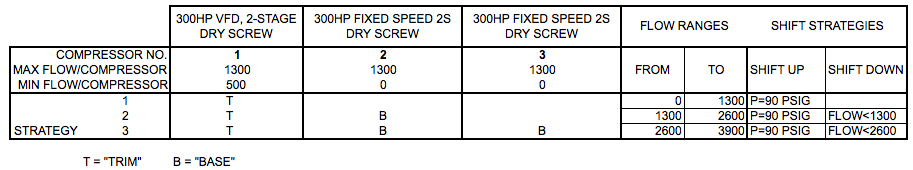
- Control algorithm. This is the intended combination of air compressors in each flow range, and the method to shift in between. See Table 1.
Figure 1. Sample P&ID, Well-integrated Compressed Air System

Click here to enlarge.
Figure 2. Flow Profile

Table 1. Control Strategies
System Commissioning Planning
System CX is the measurement, testing and adjustment of the entire system, not just the air compressor or dryer that was added. Systems are interactive. When planning this example system, which includes oil-free compressors, heat-of-compression dryers, and a master control system, the following interactive issues must be addressed:
- Heat available from compressors to regenerate dryers.
- High heat and moisture load variance on the dryers.
- Sequencing and control with a large change in flow and one VFD trim compressor.
This article can be used as a sample commissioning plan. Change the diagrams and specific descriptions, and you’re 80% there.
Testing Before Equipment is Shipped
In our experience, industrial customers tend to over-simplify air compressors as “appliances”, and don’t apply the same rigor to testing as they do to a custom, mission-critical production system. Largely because the compressors tend to be bought reactively, not proactively. Industrial plant readers, if all you did was adapt and simplify the process they already use for engineered systems, you would arrive at the conclusion that a lot can go wrong between design and start-up of a compressed air system project. You would determine that it’s cheaper and easier to catch something before it ships than after. The following is recommended:
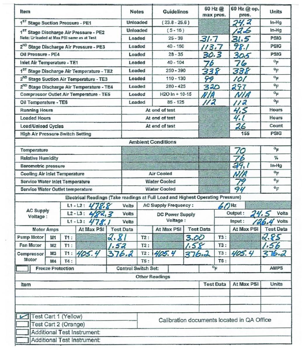
- Get a copy of each OEM’s standard test protocol, with a typical test sheet for another unit similar to the one being purchased. See Figure 3 for an example.
- Evaluate the test sheet for critical items, particularly the ones that are unique to the system as identified above and in CX planning. Add those steps in an addendum test requirement document. Having an air compressor expert engineer involved at this phase is helpful.
- Include this test plan addendum it in the purchase contract.
- Consider the value of having a witness test. This might be justified, particularly when there are several critical items that need to be tested that are not in the standard test plan. Remember that people all get stuck in their little box, and don’t communicate well with other boxes, particularly at equipment OEMs! What you say you want and what they actually do are two different things. They might not understand your intent. For instance, there are two critical items in the system described in Figure 1 that justify a witness test by the customer or compressed air systems engineer representing them:
- Compressor/dryer mechanical interaction. The dryer needs to use compressor heat to dry, and available temperature and load on the compressor are hard to predict. A factory test that couples a dryer and compressor, simulating min and max load, is recommended. In the example project, the distributor of the compressor and dryer are the same entity, so this testing is not difficult.
- Compressor controller and sequencer interface. They come from different vendors, but the master controller can easily be shipped to the compressor distributor for interface testing. The master controller can communicate with the compressor controller and change set points, start and load the compressor, at a variety of scenarios. Problems can be remedied/repaired at that time.
The typical air compressor test data sheet shown in Figure 3 has a variety of missing pieces in it that would make factory testing more valuable for this project:
- What are the set points at site? Is it being tested at those set points?
- What are the min and max outlet temperatures required for reliable operation and good dryer performance? If the temperatures are not in the range, what are the acceptable methods to adjust it (intercooler water adjustment, for instance)?
- Where are the communications testing requirements?
Figure 3. Sample Factory Equipment Test Data Sheet
After Equipment is Installed, but Before System Commissioning
Existing Air Compressor Control Modifications
In the example project, all the air compressors are new. Most projects are not replacing all compressors. If one or more of the fixed-speed compressors were existing units, the master controls become more involved, and a few more steps are needed. Each compressor needs to have the following fundamental inputs and outputs to be automated:
- Local remote switch
- Remote start/stop
- Remote load/unload
- Feedback for running, alarm and standby
- Remote set point (see below)
These can either be hard-wired, if controls are older electro-pneumatic type, or through a communications interface like Modbus, if of a more recent vintage. The remote set point would not be possible with an electro-pneumatic controller.
These modifications need to happen prior to full system commissioning, and tested. The automation company who is doing the master controller should supervise or directly do this work. They should develop an electrical schematic of the modifications needed to the compressors, and test all interfaces. Close a relay contact and see that the compressor starts, for instance.
Start-up – Major Equipment Mechanical and Electrical
“Start-up” is a phrase that is sometimes used in place of “commissioning”. It isn’t system commissioning. It precedes it. The start-up of each piece of major equipment is the supplier’s testing and documentation that each major piece of equipment is ready to run at the site, with the utilities and configuration they are in, and at the set points required. It is done according to the plan agreed on. The equipment supplier will send out their skilled technician and go through all their standard check-outs, electrical and mechanical. It should be done several weeks before system commissioning, and the equipment run in “local” controls to flush out any issues that need to be corrected before the full system is commissioned.
Pre-Commissioning Check-out
If the pieces are all checked out properly at the factory (compressors, dryer, and sequencer in this example project), very little pre-commissioning site checks are left. Mainly controls and instrumentation that are not part of the packaged equipment, and modifications to equipment.
The following can be checked by the site construction manager or engineer in charge of the project:
- Electrical connections and wiring are all in place for controls and instrumentation. The system P&ID should be adequately detailed to see where control wiring is needed, but a system electrical schematic might be needed also. Then all conduit and wires are pulled and terminations made before the system commissioning starts. Power can be validated for all components as well.
- Piping changes are done correctly. Piping sizes, valves, drains, etc should be checked out.
- In the case where some existing compressors are automated, the interface wiring/network connections are run and wires terminated properly.
Make a punch list of items that need to be addressed/repaired before full system commissioning and correct the items prior to site testing of the full system.
Site Testing
Once this is all done, site testing should be pretty straightforward. The issues that take time to correct are mostly flushed out. Now the system testing can focus on validating that the entire system operates as the customer will use it in their real operation.
Off-Line Testing
More details will be in a future article, but the basics are as follows:
- Have adequate rental compressor & dryer capacity available, or an old compressor room still available for supplying the plant during testing.
- Install temporary piping to isolate all the new tested equipment from the system, ideally with an air receiver.
- Install 2 or 3 manual bleed valves, size to create the anticipated flow range needed by the plant (see Figure 2).
- Test the combined system at the 2 or 3 flow ranges that are typical, and at the transitions between them. Tune compressor controls for optimal operation, managing energy to the lowest possible level, while maintaining pressure and dew point within specification.
- Get customer participation. This is where they get to “drive the simulator”, and learn much about the entire system.
On-line Testing:
Finally, you are ready to go “live”. This is really a validation test where the vendor/contractor team validates that the system operates for the customer, witnessed by the customer. If possible, both facility and process managers are involved, and the system operation against the typical loads are seen while all parties view the central monitoring system. In some cases, the customer needs to turn on and off production lines to validate that the peak and valley are handled well, and process control needs to be on the radio. This requires some coordination planning.
Conclusion
Don’t hope for the best without a plan. Plan and execute system commissioning in steps, starting with specification development and commissioning planning. Require testing at the OEM as part of your purchase contracts. Perform site modifications and checks, prior to full system commissioning. Finally, perform full system commissioning off-line, and then live. You will then have a system that operates smoothly and reliably for its life.
For more information, contact Tim Dugan, tel: (503) 520-0700, email: [email protected], or visit www.comp-eng.com.
To read more Air Compressor Technology articles, please visit www.airbestpractices.com/technology/air-compressors.


