By far the most important development in the world of screw type air compressors has been the introduction of variable speed control using electronic variable frequency drives (VFD’s). Systems that run with at least one air compressor at part load can almost always operate more efficiently if a well-controlled VFD is added to the system. But what if a system has two or more VFD units? This article discusses the challenges in controlling multiple VFD air compressors with some suggested solutions.
Why Use a VFD Air Compressor?
Millions of dollars of research and design work has been spent in optimizing screw type air compressors in the years since they have been developed. Innovations in rotor profiles, changes in element rotational speed, optimization of internal flow passages, upgrades to motor efficiency and many more changes have improved screw air compressor efficiencies over the past years.
The introduction of the Compressed Air and Gas Institute’s (CAGI) Performance Data Sheets certainly helps air compressor purchasers determine how much power the machines they are considering buying will consume. These data sheets show specific power, a sort of “gas mileage” rating, among other important parameters, to enable comparisons to be made. These data sheets contain important information users need to be aware of when operating both fixed-speed and VFD air compressors in single or multiple configurations.
Consider a sample 100 horsepower (hp), 125 psi-rated, air-cooled oil-injected air compressor (data not shown). This air compressor model delivers its full airflow at pressures up to 125 psig, but it was tested at 115 psig. At this pressure it delivers its measured 494 acfm of flow while it was consuming a total of 89.9 kW, at a specific power of 18.2 kW per 100 cfm. It is important to understand these numbers are valid only at full airflow, and at test discharge pressure of 115 psig. If operated at 125 psig this fixed-speed air compressor will consume about 3% more power and deliver slightly less flow. Not reported on this sheet are the operating characteristics at partial loads.
Figure 1 shows the test data for a 100 hp VFD controlled, air-cooled oil-injected air compressor from the same manufacturer. We can see the unit has been tested at 125 psig discharge pressure, 10 psi higher than the fixed-speed air compressor, and that there are five test points somewhat equidistant between points between minimum and maximum speed.
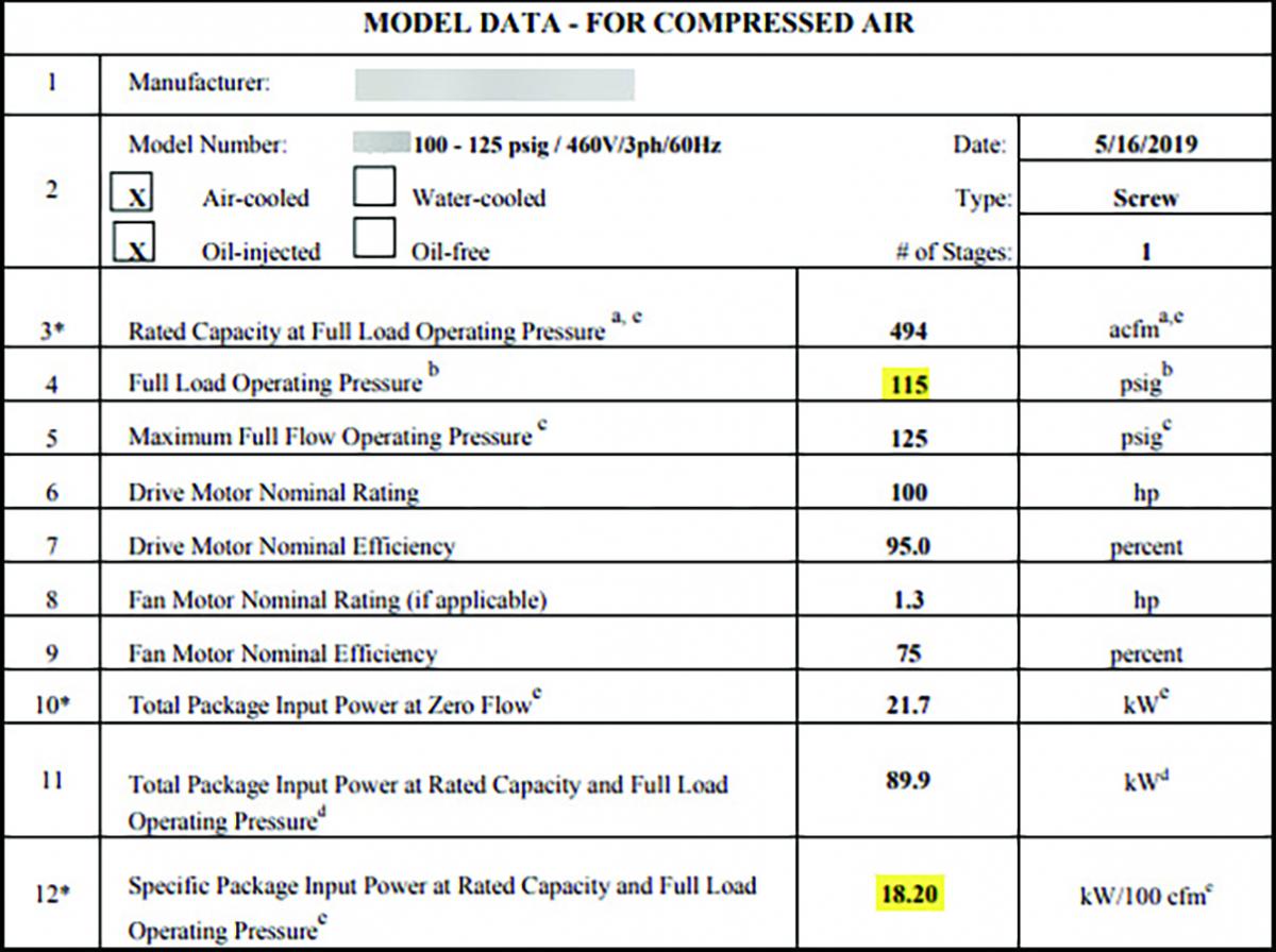
Figure 1: An excerpt of a 100 hp VFD air compressor CAGI data sheet shows the efficiency at five points of the speed curve of this 125-psi rated air compressor. The highlighted ratings are more efficient than the fixed-speed air compressor mentioned in the article. This curve has a pronounced reduction in efficiency near minimum speed.
We can see that this air compressor does not have a constant specific power through its full range of operation; there is a decrease in efficiency as the main motor speed reduces. The shape of this curve has implications if this air compressor is to be operated in a system with multiple VFD air compressors.
An observant reader might notice something interesting in that this particular VFD air compressor has higher flow, consumes more power, but has better efficiency at some parts of its curve than the comparison fixed-speed air compressor previously mentioned. This shows how the very commonly stated myth that VFD air compressors are always less efficient than fixed-speed air compressors at full load due to the drive losses is not always the case. If, however, we take a look at Figure 2, showing a different VFD air compressor of a different design, but from the same company, we see the curve is bathtub shaped, with only the middle part of the curve being more efficient than the fixed-speed air compressor. This shows us that all VFD air compressors are not alike; there are many characteristic curves, each slightly different than the others. These differences mean one type of VFD air compressor may need to be controlled differently than another.
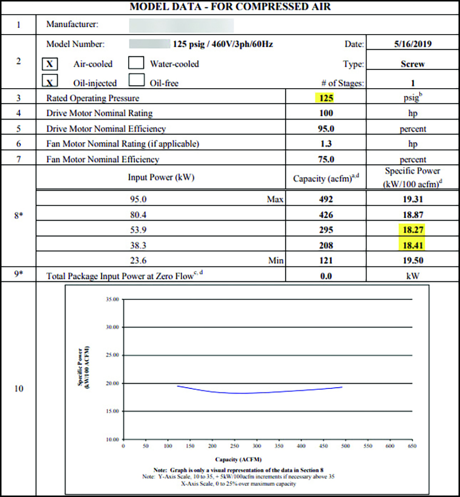
Figure 2: An excerpt of a 100 hp VFD air compressor CAGI data sheet shows the efficiency at five points of the speed curve of a different model air compressor. The highlighted ratings are more efficient than the fixed-speed unit mentioned in the article. This curve has a flat bathtub-shaped curve that is more efficient in the mid-range of speeds. Click here to enlarge.
Better Part-load Efficiency with VSD Control
For the fixed-speed air compressor, as stated previously, the manufacturer never reported part load efficiency. If we want to create the characteristic curve we must take various factors into account, like effective storage receiver size, pressure bandwidth, blowdown time, and unloaded power consumption and calculate it ourselves.
Figure 3 shows average power through the full range of operation of a typical load/unload fixed-speed air compressor with 20-second blowdown, 10-psi wide pressure band and one, two, five and 10 gallons per cfm of storage. We see on the specific power curve at the bottom of this figure that if this air compressor ran at an average loading of 40% with two gallons per cfm storage, it would have a specific power about double the full load value, or about 36 kW per cfm, well above any of the worst specific power numbers on any of the numbers in Figures 1 and 2. We can see the fixed-speed air compressor is less efficient than VFD at light loads, but is more efficient than the air compressor in Figure 2 at the highest flows of the curve. These calculations show the biggest advantage of VFD air compressor control, which is much better part load efficiency compared to load/unload control.

Figure 3: Depicted is power versus flow for load/unload fixed-speed air compressors with various storage receiver sizes. The most common size is about two gallons per cfm of air compressor capacity. The specific power curve at the bottom is for this size storage receiver. Except for the upper range of operation, part-load operation is much less efficient than VFD control. Click here to enlarge.
Typical Multiple Air Compressor Control
The typical air compressor control strategy with multiple fixed-speed units, using coordinated local control, is by setting up the air compressors in cascaded overlapping pressure bands as shown in Figure 4.
With this scheme when only one air compressor is required to satisfy the system flow, the unit with the highest pressure setting runs in part load, with the others timing out and turning off with automatic control. If the load increases where two air compressors are required, the system pressure pulls down to the load/start point of the second unit, and it will then become the trim machine, carrying part load, with air compressor No. 2 loading and unloading. The same operation continues if three air compressors are required; the two units with the highest settings would go to full load, and the third air compressor would become trim. The opposite happens as the load decreases.
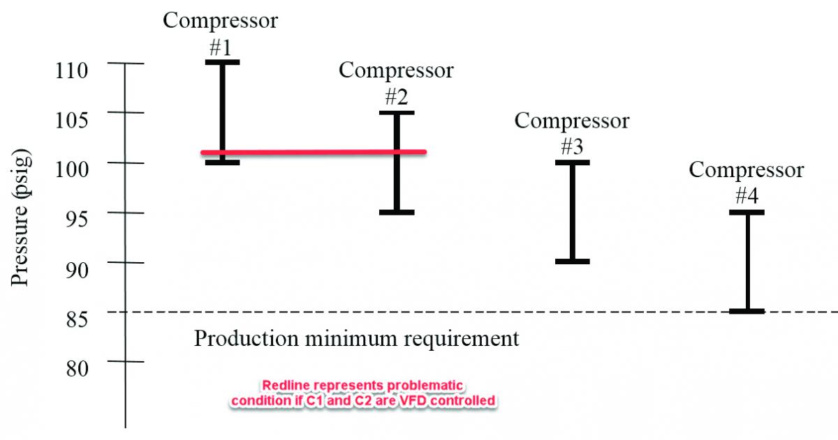
Figure 4: Shown is typical cascaded control used with multiple fixed-speed air compressors. If used on systems with multiple VFD units, some undesirable conditions can arise like at the redline point where two VFD air compressors will be running at minimum speed, where one could handle the flow. (Source: Compressed Air Challenge.)
This scheme is adequate if all the air compressors have the same part load efficiency, but the system typically suffers from higher than desired average pressure during light loads, and lower than desired pressure during high flows.
A problem happens if a VFD air compressor is introduced to the system. With VFD control, the desired condition is that the variable air compressor is always the trim unit, with the fixed-speed air compressors running fully loaded or off. This means the control scheme can’t be set to the typical cascade arrangement where all the air compressors share the trim duty one at a time. A different arrangement is needed, where the VFD target setpoint is nested within the overlapping pressure bands of the fixed-speed air compressors. This new scheme requires the VFD to be larger than the base units by about 30% or an undesirable control gap will develop where the air compressors will fight for control. This problem often causes operators to correct the situation by installing more than one VFD in a cascade-coordinated system. But this can also cause undesirable results.
Consider the condition where the system pressure is at the redline as shown on Figure 4 and air compressors No. 1 and No 2 are VFD units. The bottom of the pressure bands are the target pressures of the VFD. As such, the air compressors will try to speed up or slow down to keep the pressure constant at that setting. As the system flow drops off, air compressor No. 2 will reach its minimum speed limit, usually its least efficient point, and the system pressure will continue to rise. If the flow drops enough air compressor No. 1 will also reach its minimum speed, also its least efficient point. Since the pressure bands are overlapping, air compressors No. 1 and No. 2 will both be running at minimum speed, about 20% of full load capacity. In this condition 20% times two equals only 40% of one air compressor. This means one unnecessary VFD air compressor will be running. If both air compressors happen to have a curve like the one in Figure 1 then the result is significantly lowered system efficiency.
One solution to this problem is to stack the pressure bands of the VFD air compressors so they don’t overlap, but this means when the plant flow increases to where two air compressors are required, one of the VFD units will be at full load, the other at part load. Depending on the characteristic curve of the air compressors, as shown in the curve in Figure 2 for example, it may be undesirable to have the first unit run at full load. In this scenario there will be two distinct pressure levels, one at the target of air compressor No. 1, the other at the target of air compressor No. 2. When running at the air compressor No. 1 target setting, the system pressure will be unnecessarily high, wasting power and causing higher than desired flow due to artificial demand.
Intelligent Control with Single-Pressure Band
To avoid coordination problems, it is best to employ an intelligent system controller to orchestrate the proper operation of the system air compressors, such as in the scheme in Figure 5 where a single-pressure band is used for all air compressors.
In general, in any single system only one properly sized VFD air compressor is required for optimized control. With this condition, the VFD air compressor always needs to be in the trim position taking partial load, with all other fixed-speed air compressors being fully loaded or off. Most modern central controllers have the capability to implement this control method, and if the sizing of the VFD air compressor is correct, adequate control will be achieved with good efficiency. But some conditions can arise that could cause less than desirable operation. These are:
- The trim VFD air compressor always running at minimum speed.
- The VFD air compressor running on an inefficient part of its curve.
- The system airflow always running on the edge of the capacity of two air compressors, causing undesirable starting and stopping of the air compressors as the load changes.
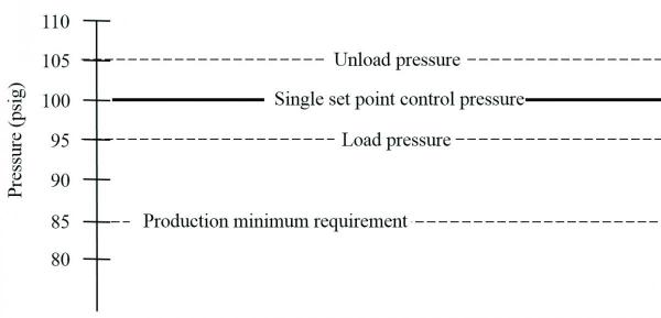
Figure 5: A central controller will enable the lowest pressure operation and will orchestrate the operation of the air compressors within a single narrow band, and preferably, with VFD air compressors, controlled at a single target point. (Source: Compressed Air Challenge.)
In systems with these conditions some special intelligent control capabilities are required, with design requirement of making multiple size combinations of VFD and fixed-speed air compressors available to the controller. Some specially designed controllers are available that can use the air compressor size combinations to mix and match machines to keep system operation optimized. These controllers typically have the following characteristics:
- The system is capable of controlling both fixed-speed and VFD air compressors at a single target setpoint.
- The various air compressor efficiency, airflow and power characteristics are programmed into the controller.
- The controller calculates total system flows based on air compressor status.
- The controller compares system flows and finds the optimum combination of air compressors to best satisfy the airflow.
- Some machine learning may be available where the controller recognizes repeating conditions, for example at a certain time each weekday, and anticipates the need for a certain combination of air compressors to avoid large pressure peaks or valleys.
- The best controllers of this type have monitoring systems that allow the operators to track system KPI’s to ensure optimal efficiency is being achieved.
For example, in Figure 6, the pressure and amp plot shows how an intelligent system controller is coordinating the operation of two VFD air compressors of different sizes and characteristics (there is a third fixed-speed spare).
There are low-load periods where it makes sense to run only one-size VFD air compressor or another size unit. The controller automatically makes this happen, but watches the system flow, and may swap out a larger or smaller air compressor as required. If the flow increases to where two air compressors are required, the controller will allow the air compressors to share the load in the middle part of the variable speed bands, where the efficiency is best, often somewhere between 40 and 80 percent flow (but depending on the air compressor curves).
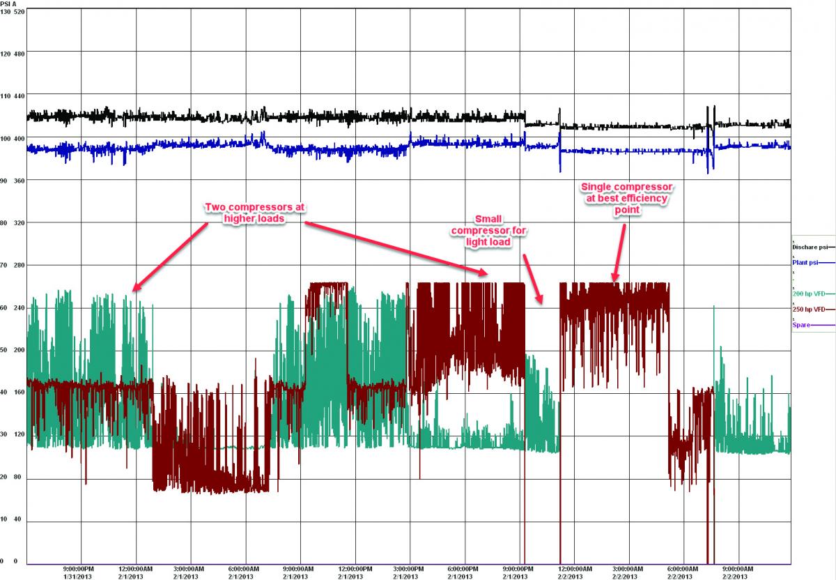
Figure 6: An example operation shows the coordination of a system of three air compressors, two of which are VFD-controlled. The air compressor characteristics are programmed into the controller and allow the optimal operation of one, or the other, or both air compressors as conditions change. Click here to enlarge.
Not all VFD Air Compressors are Alike
In most systems the presence of one or more VFD air compressors leads to better efficiency compared to a system of fixed-speed air compressors. This is due to the excellent part load efficiency of the VFD air compressors. But it is important to realize that all VFD air compressors are not alike and there are many different characteristic curves.
The best type of control is through central intelligent air compressor control where the best combination of air compressors, and best operating range, is automatically selected depending on loading conditions. Knowing the characteristics of the air compressors, this type of system keeps system specific power low by running the air compressors more efficiently, in the best loading condition, reducing the system pressure, thereby reducing air compressor power and artificial demand.
For more information about this article, contact Ron Marshall, Marshall Compressed Air Consulting, tel: 204-806-2085; email: ronm@mts.net.
To read similar Air Compressor Technology articles, please visit www.airbestpractices.com/technology/air-compressors.


