High accuracy of multiple measured parameters is critical for the development of a trusted compressed air system baseline audit. The same is true for follow-on performance validation after system improvements have been implemented. The use of data acquisition systems using Modbus-interfaced transducers can aid auditors in achieving a thorough and highly accurate system performance assessment.
There are many advantages to an audit using a network of Modbus transducers and a Modbus-capable data logging instrument. They include:
- Simplified transducer wire routing.
- Avoiding the need to compromise desired measurements due to instrumenting hassle.
- Improving measurement accuracy in an electrically harsh environment.
- Increased reliability due to fewer electrical wiring connections.
- Measured (not estimated) energy use with multi-function Modbus electrical meters.
- Collection of air compressor operation from Modbus-enabled air compressor controllers.
- Improved final audit accuracy.
What follows is a discussion about the basic function, advantages and real-world applications of Modbus transducers as deployed in data acquisition for compressed air systems, as well as other energy audits.
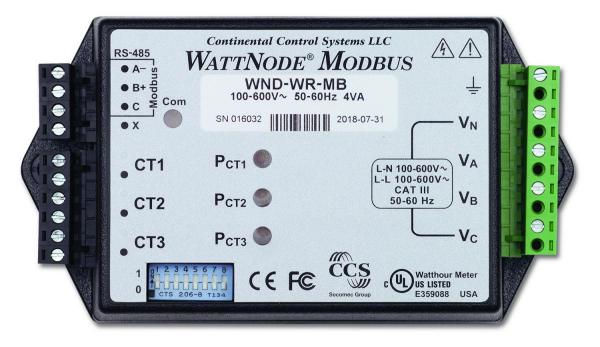
A Modbus RTU multi-phase electrical meter. (Photo courtesy of Continental Control Systems.)
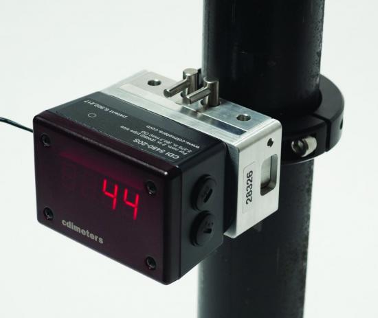
A Modbus airflow meter. (Photo courtesy of CDI Meters.)
Modbus – A Proven Technology
Modbus is everywhere in the industrial world and for good reason: It is simple and proven over time!
Modbus is a serial digital communication protocol developed by Modicon (now Schneider Electric) in the late 1970’s. Originally, it was for the company’s serial data communication in its line of industrial Programmable Logic Controllers (PLCs).
The protocol was published and released for royalty-free industry use as a standard communication path between two or more instruments, including transducers and controllers. Over the years, it has become a de facto industrial bus standard. Modbus is now the most commonly used fieldbus protocol for communications between a large array of industrial instrumentation ranging from ‘smart’ transducers to controllers to data acquisition systems.
While many faster and more secure industrial serial communication protocols exist today, Modbus continues to be implemented into instrument, transducer and controller designs and will likely continue long into the future due to its simplicity in implementation, ubiquitous installed base and open architecture.
Modbus RTU is the Modbus protocol best suited for transducers with limited microprocessor power and is by far the most common Modbus protocol implemented in transducers.
Available Modbus protocols include:
- Modbus RTU – Master/Slave topology with binary message data serial communication over RS-232 or RS-485.
- Modbus ASCII – Nearly identical to Modbus RTU, however, message data is in ASCII character format instead of binary.
- Modbus TCP/IP – Client/Server topology quite similar to Modbus RTU, however, the communication is via TCP/IP over Ethernet.
- Modbus Plus – a unique peer-to-peer protocol that allows all devices to initiate queries and responses.
In essence, Modbus is the higher-level communication protocol used to define the message format of the actual communication. Meanwhile, RS-485 is the specification for the hardware communication link. Think of Modbus as being the language (English, French, Spanish, etc.) and RS-485 as the connection (e.g., a telephone line).
Measuring Flow: A Critical Component of any Compressed Air Management System – Webinar RecordingDownload the slides and watch the recording of the FREE webcast to learn:
|
Modbus Transducers – Readily Available for Audits
Many transducers used in comprehensive compressed air applications and energy audits can be procured that include a Modbus interface. With the use of a mating Modbus-compatible data acquisition/data logging system, a thorough and accurate characterization of an energy consuming system can be simplified – with improvement in the quality of key measured parameters.
Unlike conventional analog output transducers (e.g., 4 to 20 mA), Modbus transducers sample the physical parameter (pressure, flow, power, etc.) and convert this signal into a numeric value which is stored in a memory location within the transducer. This numeric value can then be queried by a Modbus-enabled data acquisition instrument via a digital serial (typically RS-485) communication link.
Today, powerful multi-parameter electrical meters, flow meters and data logging/data acquisition instruments equipped with Modbus interfaces are available off the shelf and ready to be deployed into audit applications. The benefits of Modbus transducer technology includes:
- Excellent transducer signal immunity from punishing electromagnetic field effects.
- Ease of wiring multiple transducers.
- Fewer cost/benefit compromises in the “desired parameters versus wiring time/effort” decision.
Modbus RTU networks are comprised of Master and Slave(s) architecture. A typical network consists of one (and only one) Master device, one or more connected Slave device(s) and interconnecting network wiring. In a typical compressed air audit data acquisition system (Figure 1), the data acquisition instrument is configured as the Master and one or more transducers are configured as Slaves.
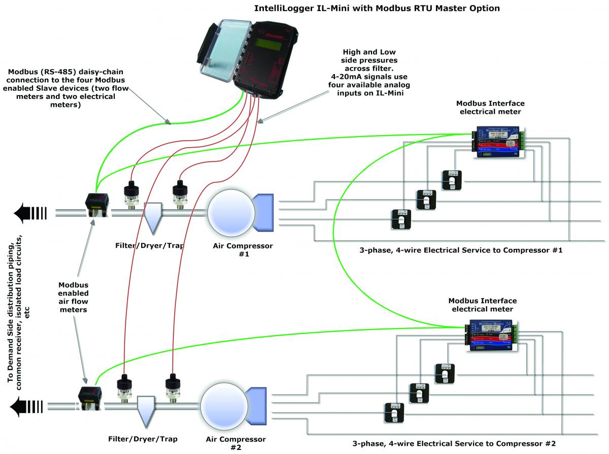
Figure 1: Illustrated is an instrumented compressed air system utilizing both Modbus and analog transducers. (Diagram courtesy of Logic Beach Incorporated.)
Modbus Slave Transducers and Compressed Air Audits
Modbus transducers with internal basic processing capability are available that measure many physical parameters needed in compressed air audits, such as pressure, flow, electrical power/energy and more.
In operation, these intelligent transducers sample the physical analog parameter (e.g., pressure) and perform local (i.e., within the transducer) analog to digital conversion. This digital resultant value is then stored to a memory location within the transducer called a Modbus Register, which has a unique identifying address associated with it.
Many Modbus transducers are capable of sampling multiple physical parameters as well as generating additional calculated parameters. For example, Modbus electrical meters can sample multiple phase currents and voltages on single- and 3-phase loads and then internally calculate 20-plus electrical parameters such as phase voltages, phase currents, power, energy, power factor, frequency and more.
Each of these calculated electrical parameters are then stored periodically to a Modbus Register memory location within the meter. In these multi-Register Slave transducers, each of the Modbus Registers will have a unique Register address.
In addition to “read only” registers, many transducers will also have “Read/Write Registers,” which may contain non-volatile calibration constants, sampling rate settings, output control, measurement units (e.g., temperatures in Fahrenheit and Celsius), or other settings configured by the user before deployment.
Slave devices may also have Read/Write registers that are updated during run-time. For example, an electrical meter may have a Register that totals energy consumed. In this case, it may have a “clear” option that resets the total to zero when a particular Modbus Read/Write register is toggled.
Before deployment, Modbus transducers all require some basic system configuration. Typically these settings are configured using generic Modbus or manufacturers’ software running on a PC. The connection between the PC and the Slave device is commonly via USB or over the Modbus RTU connection (typically RS-485). Simple commands are sent to the Slave device to configure these settings. In many simpler devices, some parameters (e.g., Slave device address) may be set via DIP switches on the unit. Basic parameters to be configured for all Slave devices residing on the network include:
- Slave device network address.
- Serial communication data rate.
- Serial data packet Stop bits and Parity.
In some installations, the actual air compressor controller is equipped with a Modbus RTU port and can be connected on the Modbus data acquisition network as yet another Modbus Slave device.
Armed with the Controller Register Map, users can configure the data logger to simultaneously garner valuable parametric data available from the controller, such as outlet pressure, run state, etc. This can save redundant installation of additional transducers to acquire those parameters. The resulting logged controller data can then be correlated with other measured compressed air system flows and pressures data.
Modbus Master Data Logger & Network Wiring
In an air audit data acquisition network, a Modbus RTU-capable data acquisition instrument, such as a Logic Beach IntelliLogger™, is utilized as the network Master. The Master instrument is then user-configured with details about the connected Slave devices and the desired Modbus Register addresses along with communication parameters. Users can also use Logic Beach’s HyperWare-II™ programming software to specify data available on an airflow transducer’s Modbus register.
Modbus RTU serial data communication between the Modbus Master and the Slave(s) is most common over a network using two or four-conductor, shielded twisted pair wiring utilizing RS-485 with a total distance of up to 4,000 feet.
Devices supporting RS-485 have internal RS-485 transceiver chips that allow multiple devices to be connected to a single-wire pair in a multi-drop topology without excessively loading the network. This allows up to 32 devices on one Modbus RTU network, typically far exceeding the Slave devices required for an audit data acquisition network.
As RS-485 is a digital hardware serial communication link, it has excellent immunity to stray electrical noise. Unlike analog signals, induced voltage fluctuations up to one Volt or more are ignored by the RS-485 transceivers. This extreme noise immunity is of great value in rejecting electromagnetic flux generated by multi-horsepower electric motors driving air compressors and adds to the accuracy and robustness of an audit data acquisition system.
Installation of the single multi-drop cable simplifies the installation of the data acquisition as one cable can be routed to allow reading of tens or hundreds of parameters. In contrast, running individual analog transducer wire pairs would result in vastly more conductors with the associated decrease in reliability due to potential conductor damage, connection failures and wire harness routing difficulty.
Data Acquisition Network Operation
Slave transducers will asynchronously and periodically sample their inputs, such as pressure, and current, perform basic analog to digital conversion and store the result in the appropriate Modbus Register. The frequency of this sampling and register update depends on the transducer. Some transducers allow users to program update rates.
While the Slave devices are sampling inputs and updating their internal registers, the Modbus Master data logger will periodically transmit a “Read” request onto the network, which will include both a Slave device network address as well as the desired internal Modbus Register address. The Slave device at the specified network address will then reply with the value in the requested Modbus Register.
The data logger receives and processes this value based on the programming defined by the auditor. Processing may include unit conversion, inter-channel calculations, time integration, min/max/averaging, summation, alarm rule checking, etc., and after processing calculations are done, the result will be stored to data logger memory or reported to the Cloud.
With a versatile data acquisition instrument, analog transducers with common analog signal outputs (4-20mA, 1-5Vdc, etc.) can also be utilized in an audit data acquisition system to measure parameters not requiring or benefitting from the power of a Modbus transducer. Modbus slave transducers and analog transducers can be installed and configured for simultaneous data acquisition, combining all acquired measurements into a single audit result file for later download and analysis.
Putting Modbus in Your Toolbox
Modbus transducers can be a powerful audit, test and troubleshooting addition for both auditors and facility managers to put in their instrumentation toolboxes. The Modbus protocol, wiring and use configuration are straightforward, making the learning curve very low – and the highly beneficial protocol is everywhere.
About the Author
David Parks has been in the instrumentation and controls industry since he graduated Iowa State University in 1977. He is President and Founder of Logic Beach Incorporated, email: dparks@logicbeach.com.
About Logic Beach Incorporated
Since 1986, Logic Beach Incorporated has been designing innovative stand-alone, network enabled and most recently Cloud-connected data acquisition, alarming and reporting instruments. Known for their intuitive icon based HyperWare-II™ programming software, simple to complex data acquisition routines can be quickly developed and deployed into their rugged IntelliLogger™ line of data acquisition instruments. Additional Modbus and instrumentation information is available at www.logicbeach.com.
To read similar Air Compressor Instrumentation articles visit www.airbestpractices.com/technology/instrumentation.


