Properly sizing a compressed air system can help determine if your facility has enough air to adequately supply your production equipment. Designing a cost effective system that minimizes any interruptions to productivity requires thoughtful planning and design. Typically, the desired outcomes of such a system focus on stable pressure and efficient operation, though it is important to note that each of these elements requires a unique solution.
Beyond those criteria, choosing the right equipment and how the air will be used are important considerations in determining the size of the air system.
For example, when an air compressor is too large for a given application, it operates at a reduced load, consuming more energy than necessary. Alternatively, air compressors that are too small for a given application are incapable of delivering the proper air supply to fulfill your needs. This can impact production time and require the purchase of another air compressor to meet demand.
When designing a system, consideration should be given to minimum, normal and maximum air demand - because your demand will likely change over time. For the highest efficiency, normal demand should be approximately 65 to 100 percent of peak output. If you know the air demand will increase dramatically, then you need to determine if the air compressor can be uprated to meet the increased demand.
As a rule of thumb, the larger the air compressor, the more efficient it is. Therefore, two units, each sized for 50% of total demand, may be less efficient than one larger air compressor running at the full load rating. If air demand is likely to be less than 50% capacity for extended periods of time then one of the smaller air compressors would likely be shut down for long periods of time, making this combination more efficient.
This article will provide guidance in proper selection considerations and suggest when a centrifugal air compressor may be ideal for your needs.
Centrifugal Technology Defined
Let us first start with the definition of centrifugal technology.
A centrifugal air compressor is a member of the dynamic-type compression technology. In dynamic compression, air is drawn between the blades on a rapid rotating compression impeller and accelerates to high velocity. The air is then discharged through a diffuser, where the velocity is transformed into static pressure.
Before selecting the right technology, the first consideration is to determine if the process needs oil-free air since many applications require that the air be entirely oil-free.
Selecting & Sizing Oil-Free Air Compressors – Webinar RecordingDownload the slides and watch the recording of the FREE webcast to learn:
|
Specifying Air Compressor Performance Requirements
The end user should specify the flow requirement - either mass flow rate or volumetric flow rate - scfm or acfm-Free Air Delivered (FAD).
There are several methods to rate the capacity/flow of an air compressor:
- Inlet cubic feet per minute (icfm) - At the intake which is referred to as the inlet volume flow or intake volume.
- acfm/cfm-FAD - Free air delivery as measured at the delivery point, after the after-cooler and is referred to the ambient conditions of the air compressor, but unaffected by it.
- scfm, or Nm3/HR - Standard or normal flow, measured at the delivery point and referred to as STP (Standard Temperature and Pressure) or NTP (Normal Temperature and Pressure) conditions.
While specifying the flow, it is also important to specify both the design inlet conditions and the reference/standard conditions for scfm and Nm3/hr. There are various reference/standard conditions as shown below.
Reference conditions for scfm:
- 14.7 psi, 60 °F, 0% (Relative Humidity) RH
- 14.7 psi, 68 °F, 0% RH
- 14.7 psi, 70 °F, 0% RH
Reference conditions for Nm3/hr:
- 1.01325 bara, 0 °C, 0% RH
- 1.01325 bara, 15 °C, 0% RH
- 1.01325 bara, 20 °C, 0% RH
Reference conditions will affect the flow, so it is noted as a best practice to specify the reference condition with your compressed air partner.
The four variables that influence the performance of centrifugal air compressors are:
- Inlet temperature
- Inlet pressure
- Relative humidity
- Cooling media temperature
It is necessary to specify the maximum/minimum and average site conditions in order to gauge performance. With dynamic compression technology, the performance will change based on inlet conditions, as will the turndown or throttle range.
Discharge pressure can be specified in psig/psia or other metric units, such as bar or kg/cm2. With respect to the discharge pressure of the air compressor outlet, a user needs to also consider that the pressure will drop in any downstream components such as a dryer, receiver tank, piping, filters that may be installed after the air compressor.
Once the flow and pressure parameters are confirmed, you need to look at the flow demand/load as this will help to size the right air compressor and avoid unload or blow off operation in order to make the air compressor run more efficiently.
|
The Compressed Air and Gas Institute (CAGI) is the united voice of the compressed air industry, serving as the unbiased authority on technical, educational, promotional, and other matters that affect compressed air and gas equipment suppliers and their customers. CAGI educational resources include e-learning coursework, selection guides, videos and the Compressed Air & Gas Handbook. The Centrifugal Air Compressor Section of CAGI consists of the following member companies:
|

Centrifugal Air Compressor Performance Curve Terminology
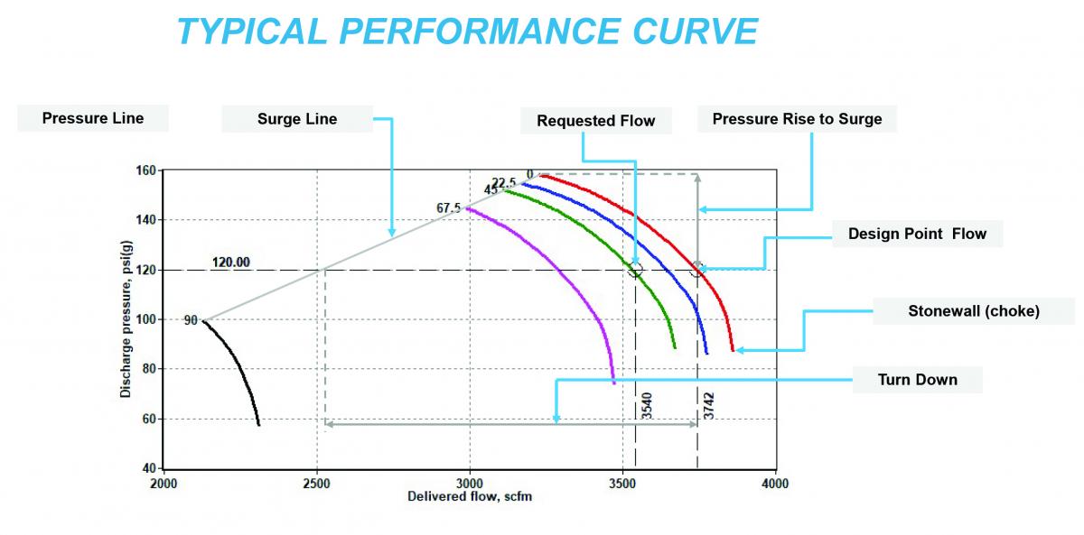
Figure 1. (Image courtesy of the Compressed Air and Gas Institute.) Click here to enlarge.
Figure 1 shows a typical performance curve at given inlet conditions, showing flow on the X axis and pressure on the Y axis. Each color curve shown above is the performance of the centrifugal air compressor at a certain inlet valve or guide vane position. For example, the red curve is at full open inlet valve (IGV) and the blue and other color curves shows performance at different position of the IGV.
- Design point is the point at which the air compressor delivers maximum flow of the chosen air compressor at chosen design conditions.
- Operating pressure and requested flow is the flow requirement specified by the end user.
- Choke notes where the system pressure continues to decrease, air delivery from the air compressor increases, and at that point no further increase in flow is possible.
- When air system pressure increases, the air compressor supplies less air until the throttle surge point is reached. At this point, the air compressor is unable to maintain a steady flow of air into the system. When this point is reached, backflow from the system through the air compressor occurs until a momentary equilibrium is established between the air compressor and the system. This backflow is referred to as surge and the line joining all the maximum pressure points of performance curves is called surge line.
- Turndown is defined as the relative difference between the maximum flow (at the design point) and minimum flow before blow-off (on the surge line) or difference between the requested flow and minimum flow before blow-off.
- The pressure rise to surge is the difference between design pressure and maximum pressure of the air compressor before going to surge.
Air Compressor Technology Monthly e-NewsletterWith a focus on Supply-Side Optimization, air compressor technologies and compressor control systems are profiled. System Assessment articles detail what compressor controls allow kWh consumption to match system demand. |
Conclusion
When sizing an air compressor, a user should select an air compressor with a minimum turndown of at least 20% and pressure rise of a minimum of 10% to avoid blow-off and guarantee an optimal energy efficient operation of the unit.
After all the inlet design data is available, a compressed air partner can help size the most optimum compressed air system to meet your flow and pressure requirements.
For more information, visit the CAGI web site at www.cagi.org.
To read more air compressor technology articles, please visit www.airbestpractices.com/technology/air-compressors.


