Introduction
In my last article, I described some fundamentals of water and air mixtures, like how much water vapor can air hold, and why. I also explained that most of the water is supposed to be removed in the compressor aftercooler, separator and drain, about 75%, leaving the last 25% to the dryer. Just 25 yards to a touchdown, one good run and you’re in. However, if the after-cooler is fouled, or the drain is not functioning, the load on the dryer can more than double. You’re 4th and 20 and at the 50. Unless the dryer is way over-sized, it won’t have a chance. Your dryer will never be able to score for you. You’re going to have to punt!
Basic Theory
Before I launch into some practical dryer system and component issues, probably more pressing to the audience, let me cover some basic theory.
Impact of Temperature on Refrigerated Air Dryer Effectiveness
To review from the last article, the maximum water load air can carry at a given pressure is solely dependent on the temperature. The temperature affects the maximum “partial pressure” water vapor can exert. Since the outlet of a compressor after-cooler is always saturated, or 100% relative humidity (RH), water vapor is at the “saturation pressure.” Thus, a higher temperature compressor outlet dramatically affects the water vapor load on the dryer. For every 10 °F increase, the mass of water increases about 35%.
Figure 1. Typical Refrigerated Air Dryer Correction Factors for Pressure
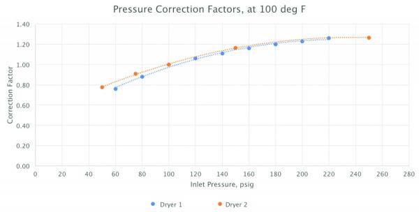
Kaeser = Dryer 1, Zeks=Dryer 2
What impact does pressure have on the water-holding ability of air? What impact does it have on the dryer’s ability to dry? See Figure 1 for two manufacturers’ correction charts for refrigerated air dryers. To answer this, I need to review some terms introduced in my last article, dig a bit deeper, and talk about pressure more.
Impact of Temperature on Regenerative Adsorption and Regeneration Effectiveness
This is more of an art than a science. Activated alumina, the typical desiccant in regenerative dryers, adsorbs moisture at high density, and releases moisture at low density. So, the adsorption efficiency declines as density reduces. Higher inlet temperature is lower density. Some manufacturers have dramatic de-rates for higher inlet temperatures, more than the refrigerated air de-rates. See Figure 2.
Figure 2. Typical Regenerative Air Dryer Correction Factors for Temperature
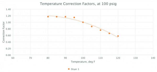
Airtek = Dryer 1
Impact of Pressure on Total Water in Air
The governing equation is:
- Water/air mass ratio = 0.622 x Pv / Ptot = 0.622 x Pg x RH / (Ptot + 14.7)
Where RH = relative humidity, the ratio of how saturated the air is, 0 to 1 ratio
Pg = “saturation pressure,” the maximum partial pressure water can
exert, fully saturated - solely based on temperature, psig
Ptot = gas mixture total “gauge pressure,” psig
0.622 = the molar mass ratio of water vapor to air (18.02 / 28.97)
Since Pg and RH are on top, temperature and humidity at any point in the air stream increase the mass of water. So, at the inlet of the dryer, this is caused by higher temperature (remember the 35% per 10 °F rule). The RH is always 100% at the dryer inlet. However, note Ptot is on the bottom of the equation. Higher pressure reduces the water/mass ratio, and the thermal load on the dryer. Pressure “squeezes out” the water vapor, turning it into liquid, and reduces the remaining water in the air. A 10 psi increase in compressor discharge pressure results in approximately 9% reduction in the water load on the dryer, and vice-versa.
Impact of Pressure on Velocity in Dryer
To simplify, higher gas velocity reduces a heat exchanger or separator’s effectiveness. The heat transfer coefficient goes up a bit, but the transmit time will reduce, decreasing the achievable temperature differential. The velocity equation is:
- Velocity increase = (Prated + 14.7) / (Pact + 14.7) - 1
Where Prated = dryer rated inlet pressure, psig (typically 100 psig)
Pact = actual dryer inlet gauge pressure, psig
So, a 10 psig lower pressure would increase velocity by about 10%. This increased velocity has multiple impacts on the dryer, including an increase in pressure drop, and a reduction of the heat exchanger's (evaporator's) effectiveness.
Impact of Pressure on Pressure Drop
Pressure drop is related to the square of velocity. As described above, velocity is related to pressure. Since we measure pressure, not velocity, the governing equation is:
- Pressure drop increase = [(Prated + 14.7) / (Pact + 14.7)]2 – 1
So, a 10 psig lower pressure would increase pressure drop by about 20%. If the original pressure drop for the dryer, filters and piping was 10.0 psid, it would now be 12.0 psid.
Benefits & Technology for Decentralizing a -40ºF Dew Point – Webinar RecordingDownload the slides and watch the recording of the FREE webcast to learn:
|
Impact of Pressure on Refrigerated Dryer Heat Exchanger Effectiveness
Based on empirical testing, refrigerated dryer manufacturers publish “de-rates” for lower pressures. Lower pressures have a larger negative impact on performance, than higher pressures' positive impact. See Figure 3 for correction factors for two manufacturers’ refrigerated air dryers. Numbers below 1.00 are de-rates. There is significant concurrence between these two manufacturers.
Figure 3. Typical Refrigerated Air Dryer Correction Factors for Pressure
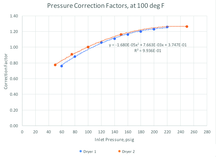
Kaeser = Dryer 1, Zeks=Dryer 2
Impact of Pressure on Regenerative Adsorption and Regeneration Effectiveness
This is also more of an art than a science. Theoretically, higher velocity creates lower retention time, reducing the desiccant's ability to adsorb the water vapor. Two different manufacturers’ correction factors are shown in Figure 4. There is significant divergence between these two.
Figure 4. Typical Regenerative Air Dryer Correction Factors for Pressure
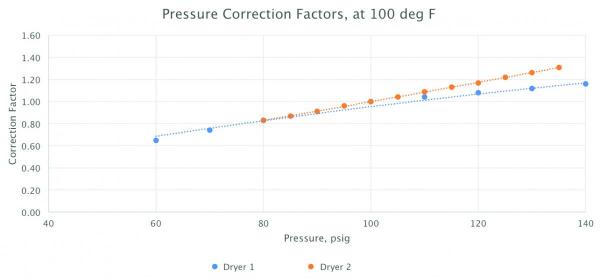
Kaeser = Dryer 1, Airtek=Dryer 2
Practical Implications
This article will now move from theory to practice, and discuss dryer package issues impacting the amount of water vapor that will be removed.
Refrigerated Dryer Package Issues
Refer to Figure 5 for a typical air-cooled refrigerated air dryer diagram, most are similar. Without going into details about dryers, the reader should know a typical dryer inlet design condition is 100 psig, 100 °F and 100% RH. See Table 1 for water removed in a 1,000 scfm system, first in the compressor after-cooler, then in a properly functioning dryer. Note the dramatic increase in dryer heat load with increasing ambient temperature.
Figure 5. Typical Air-Cooled Refrigerated Air Dryer Diagram
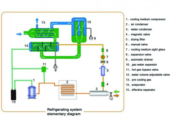
Table 1. Water Load and Removal in After-Cooler and Dryer
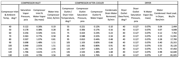
Click to enlarge.
Evaporator
The first critical component limited by the intake compressed air temperature is the evaporator. The evaporator is the fundamental heat exchanger doing the work to take moisture out of the air. When operating properly, it cools down the compressed air to just above the dew point, about 38 °F – 40 °F, to condense moisture. The refrigeration loop is a limiting factor as well. It is designed for a particular heat load and ambient temperature (if air-cooled). It has a simplistic evaporator/condensing pressure difference control through an expansion valve. See Figure 5, item #8. If the evaporator is fouled from dirty compressed air, its performance will also suffer. The temperature can quickly climb to above 60 °F at the separator, thus only providing a mediocre dew point and water condensation in the plant.
Expansion Valve
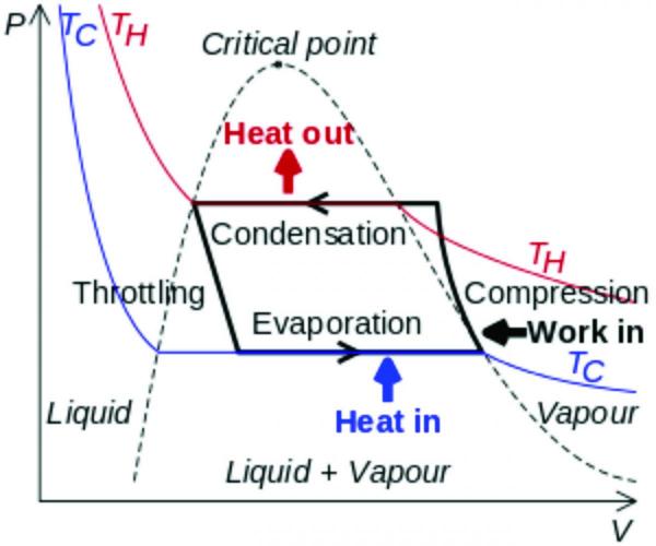
This valve is adjusted once. It controls the refrigeration pressure difference between the evaporator and the condenser. Note in Figure 6, the horizontal lines don't differ much with a given dryer. However, there's no allowance in conventional compressed air dryers for heat loads above what is designed. The pressure differential will stay fairly constant, and both the evaporator and condenser pressures (and temperatures) will just rise together as the heat load increases. The evaporator temperature will not be low enough to condense sufficient moisture from the air, and dew-point will suffer.
Figure 6. Refrigerated Air Dryer Thermodynamic Diagram
Automatic Drain
Just like in a compressor, the auto drain functioning is critical for the proper operation of a refrigerated air dryer. It drops out the mass of water it condenses. If the drain doesn’t open, liquid water will be evaporated in the re-heater, and passed downstream. All the work to reduce temperature in order to take out the moisture will be invalidated. Dew point will be equal to about the ambient temperature, and condensation will occur in the plant system.
Condenser
If the ambient temperature is too high, the condenser temperature (and pressure) rises, effectively raising the evaporator temperature and pressure along with it. This has the same effect on the compressed air cooling and condensing as the hot intake air does. Higher evaporator temperatures reduce dryer performance.
Compressed Air Purification & Piping Monthly e-NewsletterWith a focus on Demand-Side Optimization, compressed air dryers, filters, condensate management, tanks, piping and pneumatic technologies are profiled. How to ensure system reliability, while reducing pressure drop and demand, is explored through System Assessment case studies. |
Regenerative Dryer Package Issues
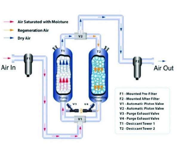
Refer to Figure 7 for a typical regenerative air dryer diagram, most are similar. The four most common types on the market, based on the type of regeneration method, are as follows:
- Heatless Regenerative (shown in Fig 7): Use about 15% of dry “purge” air to regenerate offline tower, about 10 minute total cycle, -40 °F dewpoint. They use approximately 15% energy to dry.
- Heated Regenerative: Use about 7.5% of dry “purge” air, heated, about 8 hour total cycle, -40 °F dewpoint. They also use about 15% total energy, shared between purge and heater.
- Blower Purge Regenerative: Use external ambient air, through blower, and heated, for regeneration, about 8 hour total cycle, -40 °F dewpoint. They use about 5% – 10% energy.
- Heat-of-Compression Regenerative: Use hot compressor outlet air for regeneration, cycle varies on design, -40 °F to 0 °F dewpoint. They use no energy, unless cool-down purge or trim heaters are used. There are multiple designs. Some are twin-tower, like the rest. Some are rotating drum type. They can only work with oil-free screw and centrifugal compressors.
Figure 7. Typical Regenerative Air Dryer Diagram
Valves
Dry switching valves are a maintenance concern with regenerative dryers. If they don’t seat and leak, compressed air can feed back to the regenerating tower and purge. Cool-down purge valves on blower purge dryers are rather large, and they can be stuck open as well. Finally, purge control valves can fail shut, and not dump pressure in a tower intended to regenerate. All of these failures can, and do, cause higher energy and/or poor dew point. Note, once dew point is compromised in a regenerative dryer, the bed is saturated. This can take a long time to dry out, and sometimes never can. After valve repairs causing a dryer to go wet, a new load of desiccant is often needed.
Heaters
Heaters and contactors frequently fail on heated and blower purge dryers. This not only degrades dew-point, but saturates the dryer as well.
Controls
Regenerative dryer controls are dependent on pressure sensors, temperature sensors, relays, dew-point transmitter, etc. A common issue with these controls is component failure. When one component fails, the overall controls don’t' work correctly. This can cause high energy usage, or poor dew point and bed saturation. I have seen a failed dew point transmitter fault a 6,000 scfm blower purge dryer into full cool-down purge, plus blower and full heater, costing over \$50,000/yr. just to run the dryer.
Conclusions
Compressed air dryers need to get the ball handed to them on the 25 yard-line by a compressor providing low enough temperature, and high enough pressure for the dryer to take it to the design dew point. If not, the dryer is not able to work properly. Once the dryer gets the right moisture level, it needs to operate properly. Heat exchangers, drains, switching valves, etc., all have to work with the proper control sequence to provide reliable dew point to the plant.
Recommendations
- Install an indicating and trending temperature transmitter at the inlet of the dryer, and use it to indicate when the compressor after-cooler needs cleaning.
- Install an indicating and trending dew point meter after the dryer(s). Watch the trend, and note if dew point suffers in particular circumstances, like peak load or hot ambient.
- Keep air-cooled refrigerated air dryer condensers clean, and ensure the warm air is not recirculating in from the compressor or another heat source.
- Duct the coolest and cleanest air available to an air-cooled refrigerated air dryer.
- Make sure the automatic drain on the refrigerated air dryer is functioning properly. If it is poor quality, replace it with a solid air-less drain.
- Check all dryer component and control functionality on the recommended interval.
- Perform all routine maintenance on the recommended interval.
For more information, contact Tim Dugan, tel: (503) 520-0700, email: Tim.Dugan@cmop-eng.com, or visit www.compression-engineering.com.
To read more articles on Compressed Air Purification Technology, please visit www.airbestpractices.com/technology/air-treatment.


